Post by: Ivan Beaver on April 24, 2009, 07:54:55 AM
First the basics. The arena is your typical 13,000 seat arena. It was sectioned off (curtains) so about half-2/3rds of it was being used. Not sure of how many people were there, but there were over 5K in presales-so lets say 6-7K maybe.
The PA was provided by Clair and consisted of 16 I3’s per side and 12BT218’s center clustered in the middle. Power by Lab Gruppen.
FOH was directly in front of the stage at the rear of the floor.
In the general “middle” of the floor the bass was intense and pounding very good.
OK here is where it gets weird. I did a good bit of walking around. They only allow 500 people on the floor-so it is easy to move around. As I went forward to the front of the audience –on the sides- and directly under the PA hang-the bass was GONE!!!
As I walked up the rakes on either side, the bass was just as bad. It just simply was not there. Only the lows from the main PA.
As I walked up behind FOH, it got lower (but nothing as low in level as the sides) and as I got up a little bit in the seating (say halfway) it was pretty much gone.
Evan said they were not doing anything with the bass (steering wise) and the cabinets were all run with the same signal. The cabinets were forming a sideways line array of sorts (being side by side in a row).
Basically the good sub energy was staying on the center part of the main floor (where most of the people were not)
Before anybody thinks otherwise, this is not a knock on the subs themselves, but rather an issue of the physical layout and or room interactions-and maybe something unknown.
So lets say there were 6-7K people there. With only 500 allowed on the floor. And a good number of them off to the sides down front, only maybe 300 were getting good pounding bass. Add a couple hundred more for those seated at the back of the room (most of the people in the stands were to the sides).
Now you have maybe 10% or more, of the people getting the good bass experience.
As with many discussions on sound quality at concerts here, in this case it REALLY depended where you were located. Some would talk about the pounding bass that rattled their bodies, and others would say that there was no bass at all. And they would BOTH be correct.
Sorry to rant, but I have never in my life, in all the thousands of gigs I have done, and close to a thousand installs-not to mention concerts attended, have I ever heard THAT MUCH variation of the lows/subs etc. It was simply STUNNING!
Evan did say they had been playing with different configurations on the tour. Well THAT ONE, did not work well-for the audience anyway. It was great at FOH-so I guess it really depends on who you are trying to please
On the rest of the mix, here are a couple of comments. Evan was running the screaming girls (in the audience) WAAAYYY to hot!
Being a half empty arena, there was a lot of “room” coming back and overall the sound was very cluttered. This was not due to his mix-which sounded like it would have been fine in a more tame room.
But in situations like this you do not worry about getting a “nice mix” and just concentrate on giving the audience a “Rock-n-roll” experience, and he did that just fine. The band put on a good show and the kids enjoyed it, and that is what it is all about anyway-right?
Regarding the coverage of the rest of the PA, I have no idea. I was so dumbfounded by the bass and how it was reacting, I could not even think about the rest of the system.
But I did miss the floor feeling like it was going to fall in anytime-as the last couple of gigs I have seen ATL.
Nice seeing you again Evan-=keep up the good work and you can go far in this business. We need more people who really care about how it sounds.
Keep on Rockin'
Post by: Jon Waller on April 24, 2009, 10:31:39 AM
But that would have taken away from the punch felt by the BE's at FOH. And after all, they are the provider's customers, not the 'punters' who are buying the tickets. I actually detest calling the audience that, but it is a term I have heard repeatedly used on this forum.
I know when I am thinking about plunking down money to see a show, the number one thing on my mind is whether or not it is worth the crapshoot of getting enjoyable sound. One of the best sounding, most enjoyable shows I have ever seen was free! (It was Spyro Gyra outdoors a few years ago, sitting right in front of the board).
BTW, what is the driver complement in an I3?
Post by: Greg Cameron on April 24, 2009, 12:31:29 PM
Greg
Post by: Art Welter on April 24, 2009, 01:03:53 PM
I would not think by itself a 22-24 foot “line” (assuming the cabs were tight packed, not spaced) of lows would be as directional and interact with the mains on the sides and vertically behind and above FOH unless there was significant frequency overlap,
A “J” hang with overlap, and subs time aligned at FOH is my guess for no bass on the rakes on either side, only the lows from the main PA, and the lack of bass halfway up in the seating behind FOH.
This kind of stuff makes me wonder if the set up engineers bothered walking the room, or if they did, what they were listening for.
“Evan did say they had been playing with different configurations on the tour.”
My guess is the set up guys, taking advantage of the low end output of the main hangs and trying to appease the sub hogs, ran the I3s down low.
Do you know if there was an overlap in frequency range between the thirty two I3 cabs and the twelve BT218s?
What would you estimate the distance between the main hangs was?
Art Welter
Post by: Evan Kirkendall on April 24, 2009, 01:08:30 PM
I too noticed the same thing Ivan did. The bass was great at FOH, but really disappeared off to the side.
We've tried stacking the subs 2x3 and 3x2 on either side of the stage, but the nodes still exist, only in different places.
Today we're trying to delay the outer few subs to hopefully spread the LF out some more!
Evan
Post by: Evan Kirkendall on April 24, 2009, 01:12:46 PM
The SE is pretty good and gets the rig sounding good every night, but I guess there was nothing else he could do.
Evan
Post by: Gabe Nahshon on April 24, 2009, 01:17:47 PM
Another thing I like to do is put some distance between the sub stacks and run them with no time offset. I've done this with 4 stacks of 3, spaced 10 feet apart. It was pretty even.
I believe bennet had some MAPP models floating around somewhere of a long line of subs with no time offset. Not just ugly, but Fugly.
Gabe
Post by: Gabe Nahshon on April 24, 2009, 01:29:49 PM
Post by: Phillip_Graham on April 24, 2009, 02:13:54 PM
I personally really like the horizontal line array sub setup in old-style theaters or narrow venues, where the array essentially spans the venue width. This makes for very even coverage.
If I had these 12 subs to work with, I would place 4 in the center, and the remaining 4 in a 3/1 cardiod at either end of the stage, angled out towards the audience.
Then set the delay time of the side sub arrays along the coverage seam of the center cluster where it intercepts the audience in the stands.
This PA looks like it could have used some outfill arrays, too, depending on how far the audience extended to the sides.
Another option would be a flown central subwoofer line array...
I should clarify that I like the cardiod solution more than the arced and/or progressive delay approaches because those can cause a large lobe of LF to show up right in the center of the stage.
If you are in a situation where you need defined coverage in a narrow area (such as multiple stages outdoors for a festival) the spaced horizontal array, these horizontal arrays work well to narrow the LF coverage in the horizontal.
Post by: Christian Tepfer on April 24, 2009, 02:24:41 PM
| Evan Kirkendall wrote on Fri, 24 April 2009 19:08 |
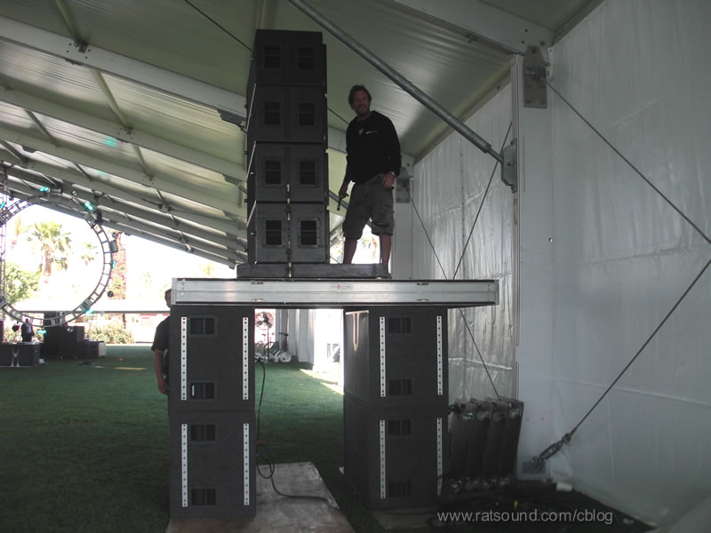
Just for reference, here's a shot of the stage from about mid ways back: I too noticed the same thing Ivan did. The bass was great at FOH, but really disappeared off to the side. We've tried stacking the subs 2x3 and 3x2 on either side of the stage, but the nodes still exist, only in different places. Today we're trying to delay the outer few subs to hopefully spread the LF out some more! Evan |
A center sub hang would give you want you want, if you can do it maybe try
Spacing in between the subs eases the beam as well...
Post by: SteveKirby on April 24, 2009, 03:22:45 PM
| Christian Tepfer wrote on Fri, 24 April 2009 13:24 |
Spacing in between the subs eases the beam as well... |
+1, not as sophisticated as delays, but very effective. The conventional wisdom (look up the origins of that phrase sometime) is to tight pack center clustered subs in order to achieve coupling and additional output. In reality, at the wavelengths involved, they will still couple without being pressed together tighter than teenagers at the prom.
There have been postings with MAAP plots showing non-delayed subs spaced out across the front of a stage and showing more uniform coverage.
If you don't want to model it, start with the acoustic centers as far apart as you can get them and still get coupling at the top of your bandpass, and then pull the outer box(s) outwards to get the spread of coverage necessary for the room.
Post by: Matthew Knischewsky on April 24, 2009, 03:26:47 PM
Here a couple quick an' dirty things to try.
Space the sub cabinets so the drivers are 1/4 wavelength apart center to center. At 80 hz thats 3.5', but with the main array going down to 80, you could probably place them about 4'-4.5' apart. This will help widen the coverage pattern in front of the stage without loosing much output, as the subs are still coupled within 1/4 wavelength.
If you have enough DSP, this is what to try next. starting with the center 2 subs at 0ms, apply .5 ms delay to each sub on either side of the center pair. Now add .5 more delay to the next outside pair, (1ms) and so on. until you get to the outsides of the array. you might not even need .5ms per pair to cover the venue, but it's a start. If you don't have enough DSP channels you can physically place the subs in an arc to create delay.
Matt
(edit spelling)
Post by: Art Welter on April 24, 2009, 03:27:19 PM
That is quite an arc going on, how many feet down stage of the subs is forward edge of the array?
Have you noticed how much acoustical overlap there is between sub and the 12”s?
I have been reading all the responses, but the lack of LF Ivan mentioned behind and above the front mix does not correlate in my mind with “too much of a good thing (directivity)”.
Art Welter
Post by: Phillip_Graham on April 24, 2009, 05:33:12 PM
| Art Welter wrote on Fri, 24 April 2009 15:27 |
Evan, That is quite an arc going on, how many feet down stage of the subs is forward edge of the array? Have you noticed how much acoustical overlap there is between sub and the 12”s? I have been reading all the responses, but the lack of LF Ivan mentioned behind and above the front mix does not correlate in my mind with “too much of a good thing (directivity)”. Art Welter |
Art,
The subwoofers are going to form a virtual dipole by coupling to the floor in the vertical plane. Whenever LF boxes are placed against a solid boundary, its important to remember the boundary causes "virtual boxes" in the floor, creating basically a 2-high subwoofer array.
That is why in cardiod sub setups you reverse the box closest to the boundary, and not farthest away. This insures the canceling boxes are closest to the center of the "virtual array", and that the vertical lobe behavior of the array is also the cardiod pattern you seek.
If the system was setup as shown, and then aligned in the vicinity of FOH, its not surprising that the relative bass amount other places in the arena was low.
Its also possible, but less likely that the slap back from the rear wall of the arena was cancelling some of the forward sub energy at important mix frequencies in the audience.
There is always the possibility of catching an unusual room mode in the acoustic space, but my guess is that this was more a function of the alignment sounding right at FOH, but causing insufficient bass in the rest of the venue due to the directivity of the bass array.
Physics is physics, and this remains the most likley explanation.
PS I don't know any of the system teching details for sure, I really don't want to seem like I am slagging on the CBA guy from my armchair. Just consider it helpful musings.
Post by: Too Tall (Curtis H. List) on April 24, 2009, 06:21:49 PM
| Phillip Graham wrote on Fri, 24 April 2009 14:13 |
It looks like a case of too much of a good thing (directivity). Delay tapering the subs will help immensely, as Gabe said. I personally really like the horizontal line array sub setup in old-style theaters or narrow venues, where the array essentially spans the venue width. This makes for very even coverage. If I had these 12 subs to work with, I would place 4 in the center, and the remaining 4 in a 3/1 cardiod at either end of the stage, angled out towards the audience. Then set the delay time of the side sub arrays along the coverage seam of the center cluster where it intercepts the audience in the stands. This PA looks like it could have used some outfill arrays, too, depending on how far the audience extended to the sides. Another option would be a flown central subwoofer line array... I should clarify that I like the cardiod solution more than the arced and/or progressive delay approaches because those can cause a large lobe of LF to show up right in the center of the stage. If you are in a situation where you need defined coverage in a narrow area (such as multiple stages outdoors for a festival) the spaced horizontal array, these horizontal arrays work well to narrow the LF coverage in the horizontal. |
Hi Phil,
Didn't you use to advocate adding a 12dB Butterworth low pass on the the left and right third of a bass sub horizontal line array.
Beside only using the center one third of the cabinets to cover the high bass where the line array would cause extremely narrow dispersion the Butterworth filter added the time delay you were looking for the outer boxes.
Another example this happened to Al Limberg at an outdoor gig.
He laid down four LAB subs accross the front of the stage which was so low that he could not stack them two high.
He was amazed at how narrow the dispersion was using only four boxes at 42" each (14' wide).
Much much narrower then what Evan was looking at.
Post by: DAVID J. SYRKO on April 24, 2009, 07:05:11 PM
Post by: Art Welter on April 24, 2009, 07:09:57 PM
I am aware the boundary causes "virtual boxes" in the floor, creating basically a 2-high subwoofer array.
In this case that would only be 90 inches or so, not enough height to impart much vertical directivity below 80 HZ.
I’m not sure what you mean by “virtual dipole”, could you explain that?
Art Welter
Post by: Phillip_Graham on April 24, 2009, 07:12:03 PM
| Too Tall (Curtis H. List) wrote on Fri, 24 April 2009 18:21 |
Hi Phil, Didn't you use to advocate adding a 12dB Butterworth low pass on the the left and right third of a bass sub horizontal line array. Beside only using the center one third of the cabinets to cover the high bass where the line array would cause extremely narrow dispersion the Butterworth filter added the time delay you were looking for the outer boxes. |
Hey Curtis,
That sounds like something I might have speculated on, and it seems like it should work, but I don't think that original idea can be attributed to me.
I first started playing with cardiod/endfire/horizontal line arrays for low frequencies a decade ago, so its conceivable I said something on the SAC list back in the day?
Post by: Phillip_Graham on April 24, 2009, 07:17:49 PM
| Art Welter wrote on Fri, 24 April 2009 19:09 |
Phil, I am aware the boundary causes "virtual boxes" in the floor, creating basically a 2-high subwoofer array. In this case that would only be 90 inches or so, not enough height to impart much vertical directivity below 80 HZ. I’m not sure what you mean by “virtual dipole”, could you explain that? Art Welter |
The second set of "virtual boxes" forms two spaced sources playing in phase and at essentially the same level, IOW a dipole.
The vertical lobing above the sub axial level would be representative of this dipole.
See Dave Gunness' excellent exposition here:
http://fulcrum-acoustic.com/wordpress/wp-content/uploads/200 8/07/comments-on-half-space.pdf
Post by: Jens Brewer on April 25, 2009, 12:29:04 AM
| Phillip Graham wrote on Fri, 24 April 2009 17:33 |
That is why in cardioid sub setups you reverse the box closest to the boundary, and not farthest away. This insures the canceling boxes are closest to the center of the "virtual array", and that the vertical lobe behavior of the array is also the cardioid pattern you seek. |
Phil, in this example, you're talking about a 2 box vertically stacked cardioid arrangement, right? One sub facing 'forward' and the other faced opposite. I just want to be clear on that since the first thing I think of when I think of cardioid subs is two boxes on the same plane spaced apart by x' with delay added and polarity reversed on the cabinet closest to the audience. Or have I pictured it wrong?
Post by: Phillip_Graham on April 25, 2009, 11:20:30 AM
| Jens Brewer wrote on Sat, 25 April 2009 00:29 | ||
Phil, in this example, you're talking about a 2 box vertically stacked cardioid arrangement, right? One sub facing 'forward' and the other faced opposite. I just want to be clear on that since the first thing I think of when I think of cardioid subs is two boxes on the same plane spaced apart by x' with delay added and polarity reversed on the cabinet closest to the audience. Or have I pictured it wrong? |
Yes I am speaking of an array of 3-4 subs stacked, with the bottom one (against the floor boundary) turned around backwards.
Depending on the sub design/size, typically one rear-facing box will balance 2-3 front firing boxes.
From a practical matter of floor space, I think one almost always has to do cardiod arrays this way, where all the boxes are in the same plane.
Post by: Kevin.Windrem on April 25, 2009, 01:35:20 PM
| Christian Tepfer wrote on Fri, 24 April 2009 11:24 |
... Spacing in between the subs eases the beam as well... |
MAPP seems to indicate increasing spacing between subs (with no delay tapering) NARROWS coverage (until the spacing gets too large, then you start seeing cancellation). 12 tight packed subs is already pretty narrow.
Post by: Mac Kerr on April 25, 2009, 05:46:55 PM
| Kevin Windrem wrote on Sat, 25 April 2009 13:35 | ||
MAPP seems to indicate increasing spacing between subs (with no delay tapering) NARROWS coverage (until the spacing gets too large, then you start seeing cancellation). 12 tight packed subs is already pretty narrow. |
Once you add the walls it gets more complicated. These are predictions for an array of 10 700HP subs tight packed standing on end. It is in a room 100' wide and 150' deep, with the subs 30' off the back wall. All the plots use a 1/3oct band centered on the specified frequency.
The first screen is done with no walls and no delay at 63Hz:
This screen is with no walls, but with a 1.5ms delay arc, no delay on the center, 1.5ms on the next boxes out, 3ms on the next, etc.
This screen is with the walls turned on, and with the same delay. that nice smooth room response doesn't look so good now.
This next screen is 31Hz with walls on, and no delay:
Here is 31Hz with the delay added, not so different from no delay.
Here is 125Hz with no delay:
And lastly, 125Hz with the delay on, hopefully this is rolled off.
How the array behaves is very dependent on frequency. It is also very dependent on the environment. The difference delay makes with no walls is easy to understand, and seems very controlled. When you add in the reflecting surfaces of the room the whole picture changes. It is easy to see why it is not so easy to make this all work in the real world.
Mac
Post by: Ivan Beaver on April 25, 2009, 06:35:02 PM
There are so many variables involved.
Getting good low freq coverage is one of the harder things to predict and to implement.
I would argue that in Evans case-put FOH where it gets pounded really good-so the engineers don't kill the subs trying to get bass when they are located in a null.
It would do ALL mix engineers to walk around the rooms they are in-not just the general are of FOH, and get an idea of what the rest of the people are hearing. It can be VERY eye/ear opening-if they care about what anybody but themselves hears:roll: .
You may or may not be able to do anything about it, but at least acknowledging it is a BIG first step.
Post by: Patrick Tracy on April 25, 2009, 09:52:42 PM
There's a lot of talk about power alley on this forum, and outdoors I've definitely heard the problem. Indoors I suspect it's a different deal, depending very much on the distances and frequencies involved. My audio instinct tells me that power alley may come in handy to keep LF off the side walls near which there will be standing waves anyway. Of course I realize there will be situations where it hurts more than helps. If you (or anyone with the tools) had a spare moment to do the predictions I'd love to see an example or two of split subs in a club sized room.
Post by: Mac Kerr on April 25, 2009, 10:24:56 PM
| Patrick Tracy wrote on Sat, 25 April 2009 21:52 |
If you (or anyone with the tools) had a spare moment to do the predictions I'd love to see an example or two of split subs in a club sized room. |
What do you mean by "club sized room"? Here is a look at a pair of 700HPs per side 30' apart. This is the same 100'x150' room.
No walls:
With walls:
Post by: Patrick Tracy on April 25, 2009, 10:46:06 PM
| Mac Kerr wrote on Sat, 25 April 2009 20:24 | ||
What do you mean by "club sized room"? Here is a look at a pair of 700HPs per side 30' apart. This is the same 100'x150' room. |
That did nicely. In general terms it's what I expected as one possible outcome, that power alley could be mitigated by the room. I know better than to generalize those results to other rooms/placements/frequencies.
[Edit] Thanks!
Post by: Mac Kerr on April 25, 2009, 10:59:31 PM
Mac
Post by: Klaus {nojunk} Zimmermann on April 26, 2009, 06:11:53 AM
| Mac Kerr wrote on Sun, 26 April 2009 04:59 |
Perfect summation only nets +6dB, but perfect cancellation is infinite. |
Post by: Art Welter on April 26, 2009, 02:11:25 PM
I would think the ceiling height would be as important as the wall relationship as far as LF room response.
It appears you can specify room floor dimensions, but what is Mapp deciding to make the ceiling height?
Art Welter
Post by: Kevin.Windrem on April 26, 2009, 02:23:54 PM
| Art Welter wrote on Sun, 26 April 2009 11:11 |
Mac, I would think the ceiling height would be as important as the wall relationship as far as LF room response. It appears you can specify room floor dimensions, but what is Mapp deciding to make the ceiling height? Art Welter |
I'd agree floor and ceiling make a major impact. However, MAPP works in two dimensions only. You can model a side view response with floor and ceiling or a plan view with walls but not both and there's no way to combine the results.
Post by: Mac Kerr on April 26, 2009, 02:27:03 PM
| Art Welter wrote on Sun, 26 April 2009 14:11 |
Mac, I would think the ceiling height would be as important as the wall relationship as far as LF room response. It appears you can specify room floor dimensions, but what is Mapp deciding to make the ceiling height? Art Welter |
Mapp does not do 3D calculations. It can only model the centerline plane of the speaker or speaker array. For this reason it cannot show you a plan view of the coverage of a vertical array.
Mac
Post by: Nick Aghababian on April 26, 2009, 03:23:41 PM
Post by: Mac Kerr on April 26, 2009, 03:26:54 PM
| Nick Aghababian wrote on Sun, 26 April 2009 15:23 |
What are the advantages of a vertical sub array? |
Since you neither quoted nor responded to the message you seem to be addressing, what are you talking about? There is nothing about vertical sub arrays in Ivan's message.
Mac
Post by: Ivan Beaver on April 26, 2009, 07:15:13 PM
| Nick Aghababian wrote on Sun, 26 April 2009 15:23 |
What are the advantages of a vertical sub array? |
As with everything there are advantages and disadvantages.
Among the advantages: Same horizontal dispertion as a single unit-ie wider coverage. With a tall enough array, less energy will go up in the air where it is not needed and energizing less of the reverberant field.
Among the disadvantages: Blocks sight lines if ground stacked, hard to get stacked high up (takes more time-ie labor), by narrowing the vertical you may not reach the seats that are high up-same problem as the seats on the sides in my post.
Unless flown, you cannot get a tall center array. Tall side stacks will exhibit various "finger lobes" based distances between stacks and varies with freq.
There is no "free lunch".
Post by: Scott Smith on April 26, 2009, 09:47:14 PM
| Ivan Beaver wrote on Sun, 26 April 2009 19:15 |
...There is no "free lunch". |
Ummm...
Post by: Ivan Beaver on April 26, 2009, 09:54:02 PM
| Scott Smith wrote on Sun, 26 April 2009 21:47 | ||
Ummm... |
Ok, maybe not everybody WANTS a free lunch
Post by: Phillip_Graham on April 27, 2009, 03:06:43 PM
| Mac Kerr wrote on Sat, 25 April 2009 17:46 |
How the array behaves is very dependent on frequency. It is also very dependent on the environment. The difference delay makes with no walls is easy to understand, and seems very controlled. When you add in the reflecting surfaces of the room the whole picture changes. It is easy to see why it is not so easy to make this all work in the real world. Mac |
Hey Mac,
Two points of subtlety, even though the point of these graphs should not be lost on anyone.
First, MAPP gives no consideration of the third dimension, which can/will change the locations of the nodes and antinodes, The diagrams can be thought of only as accurate in 2d.
Second, MAPP gives you no control of the stiffness and losses of the room boundaries. I don't know the values that Meyer has chosen, but they may or may not reflect reality. Simple (ie unrealistic) boundary conditions is typically computationally expedient, so that might be what Meyer is doing.
I am sure Perrin or one of their other modeling guys could chime in on that.
Post by: Michael Hedden Jr. on April 27, 2009, 03:46:39 PM
Am I the only person that sees a guitar bridge?
Chord.....It's been a hard days night..
Mike Hedden
Danley Sound Labs, Inc.
Post by: Mac Kerr on April 27, 2009, 04:07:43 PM
| Phillip Graham wrote on Mon, 27 April 2009 15:06 | ||
Hey Mac, Two points of subtlety, even though the point of these graphs should not be lost on anyone. First, MAPP gives no consideration of the third dimension, which can/will change the locations of the nodes and antinodes, The diagrams can be thought of only as accurate in 2d. |
True, I think I mentioned that here.
| Phillip Graham wrote on Mon, 27 April 2009 15:06 |
Second, MAPP gives you no control of the stiffness and losses of the room boundaries. I don't know the values that Meyer has chosen, but they may or may not reflect reality. Simple (ie unrealistic) boundary conditions is typically computationally expedient, so that might be what Meyer is doing. I am sure Perrin or one of their other modeling guys could chime in on that. |
Mapp does give you some control over the surface as shown in the image below. What I have not been able to make it do is make the architectural guidelines be surfaces. As far as I can tell you are limited to the box shape, although you can set the dimensions of the box. Since it is not 3D those details may be irrelevant anyway.
Mac
Post by: Phillip_Graham on April 27, 2009, 04:15:32 PM
| Mac Kerr wrote on Mon, 27 April 2009 16:07 | ||||
True, I think I mentioned that here. |
Sorry I did not see that. I guess the point I am trying to drive home is that 2d constrained solutions of the differential equations involved here is going to produce a very different distribution of modes than what is allowed by the 3d shape. The changing of the distributions of the solutions to these types of equations is the very essence of "nanotechnology" that people blather on about.
| Mac goes on | ||
Mapp does give you some control over the surface as shown in the image below. What I have not been able to make it do is make the architectural guidelines be surfaces. As far as I can tell you are limited to the box shape, although you can set the dimensions of the box. Since it is not 3D those details may be irrelevant anyway. Mac |
A rectangle (technically not a box) is computationally expedient for these situations, because you can use simple (eg periodic) boundary conditions. Also the solutions are generally stable. I wonder if the Meyer materials choices are simply changing absorption at the boundaries, or if they are doing more?
PS: The boundaries in most "real" spaces are very "floppy" in that they have low stiffness, moderate absorption, and can re-resonate with tones of their own. From what I saw presented by WSDG in "Small Room Acoustic"' at the SF AES is that properly doing these numerical solutions for real spaces is really challenging.
PPS: We have a large church here in Atlanta that has a very loud Sunday service, and very stringent requirement for noise because of its proximity to multi-million dollar condo towers. This room has poured concrete floor and ceiling, and very stiff multi-wall construction with air gaps to minimize noise. Its low frequency modal response is much more "theoretical" than most rooms due to its massive and stiff boundaries. Its a fascinating room for a case study in low frequency physical acoustics.
Post by: Phillip_Graham on April 27, 2009, 04:39:38 PM
| Kevin Windrem wrote on Sat, 25 April 2009 13:35 | ||
MAPP seems to indicate increasing spacing between subs (with no delay tapering) NARROWS coverage (until the spacing gets too large, then you start seeing cancellation). 12 tight packed subs is already pretty narrow. |
Kevin, this is correct globally in the half-sphere of coverage, but what Christian is suggesting can work practically for narrowing out the main coverage lobe.
Say you have a festival setting where all of the patrons are essentially contained in a rectangle as wide as the main stage (IOW in between the PA hangs). Here, if you don't have enough subs to make a solid horizontal array across the entire stage front, but instead you spread them out a few feet on center, the practical result will be a wider main lobe (in between the PA towers).
If the audience spills well outside of this width, like in the arena being discussed, then of course a different sub deployment is in order.
So its possible for you both to be right depending on the needed deployment
Post by: Tom Young on April 27, 2009, 06:16:07 PM
It's more akin to Django than (name your favorite 6 or 12 string guitar picker).
I'm glad you don't do drugs, Mike
Post by: Ivan Beaver on April 27, 2009, 07:37:26 PM
| Tom Young wrote on Mon, 27 April 2009 18:16 |
Thanks for pointing that out. It's more akin to Django than (name your favorite 6 or 12 string guitar picker). I'm glad you don't do drugs, Mike |
Frank Zappa didn't do drugs either, and you have seen/heard his work
Another one snuffed out to early
Post by: Luis Pinzón Arroyo on April 28, 2009, 12:52:27 AM
A pdf with it's specifications could help too.
Thanks.
Just in advance: I'm not of the "cloning guy" type.
This is a jpeg file of what I do:
It's made with 4 EAW's SB-1000 and I name it "Wide Cardioid Subwoofer"
Post by: Evan Kirkendall on April 28, 2009, 02:26:52 AM
FWIW- We have the subs center clustered with them now delayed and life is good. The bass spreads out a lot more, and still hits plenty hard up the middle. I think this is what we're going to stick with.
Evan
Post by: Christian Tepfer on April 28, 2009, 06:28:13 AM
Scroll down through the japanese menu until you reach the sound nerd speak
http://www.ratsound.com/cblog/archives/232-Day-297-March-16- Fly-to-Japan.html
Post by: Stephen Payne on April 28, 2009, 09:02:07 AM
| Ivan Beaver wrote on Fri, 24 April 2009 07:54 |
Evan was running the screaming girls (in the audience) WAAAYYY to hot! |
That's all that matters
Post by: Karl P(eterson) on April 28, 2009, 02:03:36 PM
http://www.ratsound.com/cblog/
Karl P
Post by: Bennett Prescott on April 28, 2009, 03:23:42 PM
Post by: Phillip_Graham on April 28, 2009, 03:38:49 PM
| Bennett Prescott wrote on Tue, 28 April 2009 15:23 |
So one of his requirements is that he not use cancellation techniques (read: cardioid) but then he goes and does exactly that? |
Well, Dave's implementation is actually an endfire array, with the rear sub at relative zero time.
Perhaps he will realized that cardiod is the incorrect term here, and correct his faux pas.
Post by: Scott Smith on April 28, 2009, 03:49:19 PM
Post by: Mac Kerr on April 28, 2009, 03:53:19 PM
| Bennett Prescott wrote on Tue, 28 April 2009 15:23 |
So one of his requirements is that he not use cancellation techniques (read: cardioid) but then he goes and does exactly that? |
That was my first thought as well. No reversed sub polarity reversal. Oh well.
Mac
Post by: Tom Danley on April 28, 2009, 09:08:48 PM
The problem here is a logical step by step evolution, to a subwoofer system which is it’s own worst enemy.
Everyone here knows that subwoofers, when placed close together ‘feel” the radiation pressure form the adjacent units. This “mutual coupling” raises the efficiency of the combined system by 3 dB each time you double the number of radiators and boxes.
In the ideal case here, the boxes add coherently into one more powerful source.
This acoustically small source (relative to the wavelength) radiates in all directions equally unless there is a physical boundary or the enclosure is large enough to have a local effect.
What might be less clear is that this unilateral coherent addition only works up to a point, a point set by the physical dimensions of the combined array.
At the point the farthest radiators in the array become about ¼ wavelength apart, they start to NOT add coherently and begin to cancel out in some directions and add in others.
For example two equal amplitude and phase sources, one half wavelength, apart produces a figure * radiation pattern if viewed through one plane like a polar plot or a 360 degree radial lobe off axis or broad side and a deep nulls at both ends on axis if viewed in 3d.
As one increases the acoustic spacing between the sources, the polar patterns have more lobes and nulls.
The graph is a Mathcad plot, it is not a fancy muffler or drinking glass but a stack of polar plots starting at the bottom at 1/10 wavelength spacing between sources (coherent addition), progressing upwards to a spacing of several wavelengths.
How large is the subwoofer array?
What one would measure from that system would be the sum of all the separate driver to driver interactions like this, at each frequency involved.
Understand too, this complex self interference effect is not limited to subwoofers but applies at all frequencies, anywhere any two sources (or reflections) add, that are N half wavelengths different in path length, you get a null, the closer the two sources are in amplitude, the deeper the null is etc etc..
This exact problem “source self interference” or rather not having it, has been the object of much of my work in the last 20 years or so. The idea of the Synergy horn is to eliminate this self interference and let the horn define the radiation pattern.
It was the incoherent addition that turned the old large concert arrays into a loud roar I had thought. Just like the subwoofers mentioned here, the system’s acoustical size and shape is it’s own worst enemy.
Anyway, If the subwoofer array were operating up to say 80Hz and you wanted them to all add fully coherently into one source in time and space, then the largest dimension the array of sources could have would be about 1 / 4 wl at 80Hz (about 3.5 feet) or 1 / 3 wl at the most at 80Hz. Beyond that dimension, one is moving towards the “self interference” mode where what you measure depends on both the angle on / off axis as well as distance from the system. Even an homogenous source (one source or a number of them but close enough together) has strong directional properties once the acoustic size is sufficient.
For example, if one had a compression driver that produced a plane wave, a one inch exit is already large enough to confine the radiation angle entering a horn to about 60 degrees at 20KHz. Trying to get more or using a driver which produces an undesirable wavefront at the exit, are prone to produce refractions (non-axial internal reflections) inside the horn, one of the things that can give a horn a bad musical sound.
Anyway If they only wanted the low bass, then they could limit the maximum spacing to 1 / 4 WL at 30Hz so that at least these frequencies added coherently. This limits the maximum dimension to about 9 feet.
Basically, once the source size is acoustically large enough to impart directivity, then it is also too large to be adding coherently.
In addition to the goofy radiation pattern, another down side of incoherent addition of a large array of sources is an impulsive (brief wide bandwidth signal) signals arrive at the speaker terminals at the same time but due to differing path lengths from the sources to microphone, disperse or spread out the impulsive signal in time.
This last problem of course can be fixed with time delays etc, but only for one point in space.
What about a phased array?
A curved line of subs, or time delayed to make a curve is conceptually a solution, subjectively, it may well be better than a flat broad side array.
The big but “I like big butts and I cannot lie” well he might but the big but here is how sound propagates is in 3 dimensions, your dealing in 2 only with a curved line.
A sound pressure radiates according to the local gradient when the source is small, this means that it propagates spherically (towards a lower pressure) unless bounded perpendicular to the radiation angle in which case one has a partial spherical segment (such as conceptually from a high frequencies out of a pyramidal or simple conical horn or from a small source on a large baffle).
The problem with a curved array is that what you’re trying to create (again a spherical patch), one needs to construct it in the horizontal and vertical planes.
A big wide sub array, even if curved, would project a strong lobe forward and have complex cancellation to the sides as noticed, but also, on flat ground, that “power lobe” extends upward and rearward as well. One might equate this to “pattern flip” of an asymmetric horn.
Here, with the existing Pile-O-Subs, I believe the best-case minimum “interference problem” with this array would occur when the total pile is twice the width of its height.
The height is “half” because it is on a boundary which doubles its acoustic size in that plane, sound fooled by a mirror image haha.
If the edges were delayed RE; the center, this would work to help produce a spherical patch.
Alternately, a “Mastaba” of subs would be another possibility, again, twice the width and depth as height. This places the larges number of sources in the smallest driver to driver spacing and would produce the least self interference with this volume of boxes.
I would bet a 2 wide by 3 high pile of Lab subs would be pretty much of a step up for the majority of the audience, no self interference in that layout ,some forward directivity and certainly would sound tight (less dispersive in time)..
If you picture what the flare look like in that, you can envision them coupling into one source.
What would I do (wearing my speaker company hat)?
You avoid the problem right at the source by fundamental design.
In this case I would try 8 or 10 TH115’s which should be comparable in total usable acoustic power but physically smaller.
I would stack them 2 wide with the mouths at the center and 4 or 5 high.
An array of 8 TH-115s (2X4)has a radiation pattern that is very broad and reaches –6dB at 90 degrees R and L off axis, just one big broad lobe out front and a null to the rear.
That array has a simple non-interfering radiation pattern because the mouths add together at a dimension smaller than ¼ wl at 80Hz in the center of a flat baffle (the rest of the enclosure front) and forms a single 180 degree wide horn..
The real issue here, the reason they tried so many woofers and had this problem is insufficient power density. That “logical” progression to “more boxes” forcing the use of an arrangement of sources, which does not allow to coherent addition / produces an interference above a certain number of enclosures and frequency.
If one did this job with one small / powerful enough subwoofers, everyone would have low end so far as radiation pattern is concerned. So far as “making the room go away”, that’s where that D-9 or D-11 cat comes in.
A last thought, maybe the single most re-occurring thing working in sound and sound sources, with sound, one has to think of “acoustic size”, not in inches because acoustic size is related to frequency as well as inches, two fixed sources become acoustically farther apart as the frequency climbs.
Anyway, some semi random thoughts on the subject.
Best,
Tom Danley
Post by: Dave Rat on April 28, 2009, 11:22:45 PM
| Phillip Graham wrote on Tue, 28 April 2009 20:38 |
Well, Dave's implementation is actually an endfire array, with the rear sub at relative zero time. Perhaps he will realized that cardiod is the incorrect term here, and correct his faux pas. |
Hello Phil,
Well lets see, my understanding is that 'cardioid' is a mathematical shape that resembles the response patterns of unidirectional microphones where in the maximum rejection is 180 degrees off axis.
Resembles is the key word here in that I dot believe anything in the real world actually exhibits a true cardioid pattern.
By the term 'Cardioid,' in the context of the Coachella sub setup, I am referring to setting up clusters of L- Acoustics SB28 sub-woofers in a the factory 'cardioid' configuration that offers minimum output 180 degrees off axis. Though this is a frequency dependant response, the term cardioid is a useful description.
Also of note, an end-fire array can be quite easily be setup such that there is minimum output 180 degrees off axis and maximum output on axis which also resembles the cardioid shape.
Post by: Dave Rat on April 28, 2009, 11:50:35 PM
| Mac Kerr wrote on Tue, 28 April 2009 20:53 | ||
That was my first thought as well. No reversed sub polarity reversal. Oh well. Mac |
Interesting observations yet based on an incorrect assumption and I personally am not a fan of cardioid subs except...
These sub stacks with rear firing subs do implement a reversal in polarity.
They achieve that directional sub output with out dumping power and speakers into trying to take sound away from behind.
My words were 'destructive sound' and though I purposely skirted being too technical and took some liberties in descriptions, what I was describing is my avoidance of the whole 'noise cancelling concept' where anti-sound is being created as well as staying away from graduated delays that chew up power and sound funky.
Simple, clean and maximum summation in the listening area achieved with careful placements and minimum time shifts while realizing rejection benefits onstage and behind the arrays was the goal. And it worked out pretty well as the predictions were quite close to the real world.
Fun stuff!
Post by: Phillip_Graham on April 29, 2009, 12:24:36 AM
| Dave Rat wrote on Tue, 28 April 2009 23:22 | ||
Hello Phil, Well lets see, my understanding is that 'cardioid' is a mathematical shape that resembles the response patterns of unidirectional microphones where in the maximum rejection is 180 degrees off axis. Resembles is the key word here in that I dot believe anything in the real world actually exhibits a true cardioid pattern. |
I too, understand it to mean the same thing as you do, so perhaps I am parsing hairs.
That said, though, cardioid microphones typically implement their pattern by a physical acoustic delay from the microphone porting coupled with a polarity inversion on rear diaphragm. If such a concept is extended to subwoofer systems, then it would make sense to label bass systems that function in the same manner as cardioid.
| Quote: |
By the term 'Cardioid,' in the context of the Coachella sub setup, I am referring to setting up clusters of L- Acoustics SB28 sub-woofers in a the factory 'cardioid' configuration that offers minimum output 180 degrees off axis. Though this is a frequency dependant response, the term cardioid is a useful description. |
Absolutely, and certainly not a big enough point of complain to warrant a snarky comment on the blog. I am sure its plenty of information, and offers a good descriptor to most of your readership, if not to tweaksters like myself here on the LAB.
| Quote: |
Also of note, an end-fire array can be quite easily be setup such that there is minimum output 180 degrees off axis and maximum output on axis which also resembles the cardioid shape. |
I think the typical endfire array configuration is usually trying to mimic my rigid definition cardiod array. There are indeed a whole range of cardioidish shapes that can be described mathematically on an endfire array depending on the physical spacings and delay times.
Please know I am not getting down on your solution at all! My original response was essentially saying I would do it the same way you do, only with cardiod arrays rather than your sub cannon arrays (which are really endfire arrays). I almost linked to one of the early sub cannon blogs you wrote.
Post by: Brandon G Romanowski on April 29, 2009, 12:57:56 AM
Awesome post. I particularly like ""Mastaba" of subs".
Regards,
Brandon
Post by: Dave Rat on April 29, 2009, 02:23:18 AM
All good, I think there is some confusion between the Peppers sub setup that used a conventional sub setup with progressive delays on the side pointing subs to increase coverage (sub cannons, end-fire arrays, ladder arrays, cardioid or shotgun arrays, or whatever anyone wishes to call them, no difference to me as communication is the goal, semantics are just a stumbling block) and the recent Coachella setup that we used 6 cardioid (directional) sub clusters consisting of two primary cardioid clusters, two secondary forward facing outside cardioid clusters that quasi or softly end-fire to expand coverage and two central cardioid clusters time focused at mix that reduce and smooth out power alley.
Personally, I currently prefer to figure out the sub layouts using experience, some vectors, distances and math. Mainly due o the disconnect between sub prediction software and real world experience. By that I mean, the most exciting sub layouts visually in software predictions tend to be more of an exploitation of the flaws in the software than a revolutionary concepts.
But hey, the more wrong I become in that, the better tools we have to work with. So it is a win win.
I will say with some skepticism, that my most recent adventure into sub prediction software world has matched quite well with real world results. Though I moderate that with the fact that did not even try and predict scenarios that I knew were flawed.
Post by: Clarke LaPlante on April 29, 2009, 06:46:03 AM
Interesting, considering that I was led to believe y'all were doing some sort of a cardioid sub array last week at Coachella. The 22 or so deep K rig sounded alright (where I was... behind the rig). One of these days you'll come up on stage so I can shake hands with ya!
-Clarke
Post by: Mac Kerr on April 29, 2009, 11:09:00 AM
| Dave Rat wrote on Tue, 28 April 2009 23:50 |
Interesting observations yet based on an incorrect assumption and I personally am not a fan of cardioid subs except... These sub stacks with rear firing subs do implement a reversal in polarity. They achieve that directional sub output with out dumping power and speakers into trying to take sound away from behind. My words were 'destructive sound' and though I purposely skirted being too technical and took some liberties in descriptions, what I was describing is my avoidance of the whole 'noise cancelling concept' where anti-sound is being created as well as staying away from graduated delays that chew up power and sound funky. Simple, clean and maximum summation in the listening area achieved with careful placements and minimum time shifts while realizing rejection benefits onstage and behind the arrays was the goal. And it worked out pretty well as the predictions were quite close to the real world. |
Isn't the system you used exactly what you said you didn't want? The rear facing box is just that, a "noise canceling" signal. By using delay instead of polarity you were able to have control over the frequency range it worked at, but the net result is the same. The rear facing box produces an out of phase (not polarity) signal that cancels the signal to the rear (over some specified range), and adds to the signal toward the front. The same as other cardioid arrays.
My original comment was only in relation to the seeming contradiction in your blog post. It seems you came up with a very effective solution. Congrats on the K-1s.
Mac
Post by: Ken Freeman on April 29, 2009, 11:12:55 AM
Sometimes we have to choose between having a show and not having a show and being able to steer the energy towards the crowd and away from peoples homes. This can mean the difference between a viable venue and one that may never get another concert permit again. We know better than to think one of the up and coming engineers is going to abide by any noise constraints that we give them. Its like the speed limit on California Freeways. We, as providers are then challenged to control the audio that comes out of the show as best we can so that the venue and the show remain viable. We have and do play the cardioid game because it does seem work.
Nice work!
Ken
Post by: Dave Rat on April 29, 2009, 03:13:31 PM
| Mac Kerr wrote on Wed, 29 April 2009 16:09 |
Isn't the system you used exactly what you said you didn't want? The rear facing box is just that, a "noise canceling" signal. By using delay instead of polarity you were able to have control over the frequency range it worked at, but the net result is the same. The rear facing box produces an out of phase (not polarity) signal that cancels the signal to the rear (over some specified range), and adds to the signal toward the front. The same as other cardioid arrays. My original comment was only in relation to the seeming contradiction in your blog post. It seems you came up with a very effective solution. Congrats on the K-1s. Mac |
I am not sure I agree that the net result is the same. In the out of polarity scenario, the louder the rear facing box is, the quiter it gets in front till you reach a null. Here you have a subtractive scenario where max voulume on axis is achieved by turning the front speakers to full and turning off the rear speaker.
With a time aligned rear facing, turning up the rear firing box increases volume in the front. So there is a purely additive scenario where max volume on axis is achieved by turning the front and rear speaker up all the way.
Hence the destuctive versus constructive dividing line that I was not very good at clarifying.
Post by: Tom Danley on April 29, 2009, 03:33:44 PM
Do you mean (I think) an “end fire array” in antenna terms?
This is not the same as a cardoid array at all as you suggest.
The arrays like Mike and Ivan have installed work well but are still limited by the room of course.
As I recall, a spacing between each source of about ¼ wl at the highest frequency gave the best array directivity per number box used.
These were set up with the front box delayed the most and the rear with no delay etc and are on axis, an additive array.
In the concert thread here, this would be a way of reducing the frontal area of the array down to non-interfering dimensions if they could afford to occupy the depth.
Best,
Tom Danley
Post by: Mac Kerr on April 29, 2009, 03:59:31 PM
| Dave Rat wrote on Wed, 29 April 2009 15:13 |
I am not sure I agree that the net result is the same. In the out of polarity scenario, the louder the rear facing box is, the quiter it gets in front till you reach a null. Here you have a subtractive scenario where max voulume on axis is achieved by turning the front speakers to full and turning off the rear speaker. With a time aligned rear facing, turning up the rear firing box increases volume in the front. So there is a purely additive scenario where max volume on axis is achieved by turning the front and rear speaker up all the way. Hence the destuctive versus constructive dividing line that I was not very good at clarifying. |
In either case you have to use a time offset between the front and rear firing speakers. If all you do is put 1 effectively omni speaker out of polarity with the rest you get no pattern control, and you get cancellation to the front and rear equally as you say. My point was merely that the rear facing speaker is in fact creating pattern control via cancellation. Whether or not the rear facing box is in or out of polarity will have less effect than the time offset between the boxes. Below are 3 models, the first is with the bottom rear facing box out of polarity, and delayed by 4ms. The second is with all 3 boxes with the same polarity, but the forward facing boxes delayed 4ms. the third is with the bottom box out of polarity, but no delay. It is clear this is not useful. This is a half space model at 63Hz, the gain is the same to all speakers. The cancellation and forward gain characteristics will change with frequency, but can be similar in either scenario.
Post by: Mac Kerr on April 29, 2009, 04:19:35 PM
Mac
Post by: Bennett Prescott on April 29, 2009, 04:41:54 PM
Post by: Brandon G Romanowski on April 29, 2009, 06:45:20 PM
Post by: Dave Rat on April 29, 2009, 07:22:31 PM
| Mac Kerr wrote on Wed, 29 April 2009 20:59 |
In either case you have to use a time offset between the front and rear firing speakers. If all you do is put 1 effectively omni speaker out of polarity with the rest you get no pattern control, and you get cancellation to the front and rear equally as you say. My point was merely that the rear facing speaker is in fact creating pattern control via cancellation. Whether or not the rear facing box is in or out of polarity will have less effect than the time offset between the boxes. Below are 3 models, the first is with the bottom rear facing box out of polarity, and delayed by 4ms. The second is with all 3 boxes with the same polarity, but the forward facing boxes delayed 4ms. the third is with the bottom box out of polarity, but no delay. It is clear this is not useful. This is a half space model at 63Hz, the gain is the same to all speakers. The cancellation and forward gain characteristics will change with frequency, but can be similar in either scenario. |
Not disagreeing that there will be cancellations due to time or physical distance offsets but that is a such a fundamental given when dealing with multiple sub clusters that I am not sure saying it adds any relevant info.
And of course it creates pattern control through cancellation. And of course, the key is to minimize the cancellation in the desired areas of coverage.
It is distilling useful methods, which I feel is the important aspect.
"Am I ok with a wide smooth coverage pattern except there are two huge cancellation nodes but everywhere else is fine?"
"Ok, we have all the subs set for minimum cancellations but all we have is a giant power alley"
"Hey, with a center sub column we are all good everywhere but the band is getting creamed with low end and there is a sub column in blocking sight lines"
So I ask myself, "How can I cover this space, efficiently, with finesse, minimizing brute force (lossy) methods.
So how would I explain it super simply? How do I describe a desire to set up a subwoofer system wherein I wish to maximize output, coverage and efficiency while strongly avoiding any on axis reductions in output and avoiding having to add boxes to make up for sound lost due a lossy design?
I chose "avoiding destructive sound" to try and convey my desire to avoid the situation of #A "adding more to get less" and to embrace #B "using less to get more."
I do realize those concepts have overlaps when you start to include off axis response and coverage patterns and it can be unravelled in many directions but I also believe that the general concept is pretty straight forward and various setups fall closer to one side than the other.
Beam steering subs for example tends to be a lossy setup where you need more subs to cover a given area so it is more of a #A. Out of polarity speakers used for cancellation are also more of a #A because you are adding amps and speakers to reduce. While the time delayed reversed sub is more of a #B in that it does not require more gear, offers almost no drop in level on axis and improves directionality somewhat.
And perhaps that makes sense or perhaps not and hence the landmine upon which I so enjoyably have stepped.
Post by: Mac Kerr on April 29, 2009, 07:58:32 PM
| Dave Rat wrote on Wed, 29 April 2009 19:22 |
So I ask myself, "How can I cover this space, efficiently, with finesse, minimizing brute force (lossy) methods. |
I'm with ya as far as covering the space efficiently, I guess what I'm missing is exactly what is the "brute force, lossy" method. Most of the steering methods I am aware of (and I admit to not having done it as much as you have) involve using part of the sub array to create a signal that is out of phase the rear direction, and in phase in the forward direction. Since in their useful band most subs are nearly omnidirectional, there will always be a mixing of signals in both the rearward and forward directions. What kind of array (that's not just poorly deployed) only causes destructive combining in the rear direction without also causing constructive combining in the forward direction. I assume we can agree that an array that causes destructive combining in all directions is just not a useful design. It is the combination of the positive forward summing and the negative rearward summing that causes the SPL difference in the coverage.
Mac
Post by: Ivan Beaver on April 29, 2009, 08:46:48 PM
Some simple things like the number of cabinets, physical distances- and delay/polarity applied would be very helpful.
Post by: Dave Rat on April 29, 2009, 09:42:37 PM
| Mac Kerr wrote on Thu, 30 April 2009 00:58 | ||
I'm with ya as far as covering the space efficiently, I guess what I'm missing is exactly what is the "brute force, lossy" method. Most of the steering methods I am aware of (and I admit to not having done it as much as you have) involve using part of the sub array to create a signal that is out of phase the rear direction, and in phase in the forward direction. Since in their useful band most subs are nearly omnidirectional, there will always be a mixing of signals in both the rearward and forward directions. What kind of array (that's not just poorly deployed) only causes destructive combining in the rear direction without also causing constructive combining in the forward direction. I assume we can agree that an array that causes destructive combining in all directions is just not a useful design. It is the combination of the positive forward summing and the negative rearward summing that causes the SPL difference in the coverage. Mac |
A simple example is a long wide straight sub array wherein it is delayed to simulate a curved array by using gradually increasing delay times. The center sub would be zero in time and each sub outward would have a bit longer delay.
While this method can achieve a fairly smooth widening of the coverage, it is a lossy design wherein db's are lost in the coverage area due to the graduated delay times. Conversely, actually stacking the subs in a curve will be a more efficient and better sounding option that is less lossy. Though space limitations can be an issue.
Therefore, the simulated curve would need more power and boxes to reach the same output as the actual array and not sound quite as good. Basically brute forcing one shape to act like another shape and to do so we need to throw power and processing at it.
It is tempting to use these lossy solutions because they paint pretty picture in the software and often can fit into the environment we operate easier but my experience has been that they rarely work as well or sound as good as they look. Hence the avoidance and the quest for more finesseful solutions.
That said, in some situations, these lossy types of solutions can be very effective. It is just about using the right tool for the job.
For the Coachella job with some of the best rock and country music engineers coming through, it was important that there was nothing about the setup that could be disliked or pointed to as a flaw. I guess that is what Scott Sugden and I were trying to outline when defining the system design.
I very much enjoy this message board chat with you as it helps keep me thinking and refining. Thank you!
Post by: Mac Kerr on April 29, 2009, 09:55:39 PM
| Dave Rat wrote on Wed, 29 April 2009 21:42 |
A simple example is a long wide straight sub array wherein it is delayed to simulate a curved array by using gradually increasing delay times. The center sub would be zero in time and each sub outward would have a bit longer delay. While this method can achieve a fairly smooth widening of the coverage, it is a lossy design wherein db's are lost in the coverage area due to the graduated delay times. Conversely, actually stacking the subs in a curve will be a more efficient and better sounding option that is less lossy. Though space limitations can be an issue. Therefore, the simulated curve would need more power and boxes to reach the same output as the actual array and not sound quite as good. Basically brute forcing one shape to act like another shape and to do so we need to throw power and processing at it. It is tempting to use these lossy solutions because they paint pretty picture in the software and often can fit into the environment we operate easier but my experience has been that they rarely work as well or sound as good as they look. Hence the avoidance and the quest for more finesseful solutions. That said, in some situations, these lossy types of solutions can be very effective. It is just about using the right tool for the job. For the Coachella job with some of the best rock and country music engineers coming through, it was important that there was nothing about the setup that could be disliked or pointed to as a flaw. I guess that is what Scott Sugden and I were trying to outline when defining the system design. I very much enjoy this message board chat with you as it helps keep me thinking and refining. Thank you! |
Thanks, I grok the difference between the real and simulated curve array. This has been enlightening for me as well. If you or Scott have thoughts on using all pass filters to use phase change instead of delay to create the cardioid effect I would love to hear about it. With a delay offset we get the response we want over an acceptable limited bandwidth, but maybe with phase we could broaden the band, and make the coverage more even relative to frequency.
Mac
Post by: Charlie Zureki on April 29, 2009, 09:56:31 PM
| Dave Rat wrote on Wed, 29 April 2009 20:42 | ||||
A simple example is a long wide straight sub array wherein it is delayed to simulate a curved array by using gradually increasing delay times. The center sub would be zero in time and each sub outward would have a bit longer delay. While this method can achieve a fairly smooth widening of the coverage, it is a lossy design wherein db's are lost in the coverage area due to the graduated delay times. Conversely, actually stacking the subs in a curve will be a more efficient and better sounding option that is less lossy. Though space limitations can be an issue. Therefore, the simulated curve would need more power and boxes to reach the same output as the actual array and not sound quite as good. Basically brute forcing one shape to act like another shape and to do so we need to throw power and processing at it. It is tempting to use these lossy solutions because they paint pretty picture in the software and often can fit into the environment we operate easier but my experience has been that they rarely work as well or sound as good as they look. Hence the avoidance and the quest for more finesseful solutions. That said, in some situations, these lossy types of solutions can be very effective. It is just about using the right tool for the job. For the Coachella job with some of the best rock and country music engineers coming through, it was important that there was nothing about the setup that could be disliked or pointed to as a flaw. I guess that is what Scott Sugden and I were trying to outline when defining the system design. I very much enjoy this message board chat with you as it helps keep me thinking and refining. Thank you! |
Hey Dave,
How about a double "arc" of subs.
The subs set as you describe above and a rear facing line of subs similarly delayed yet with inverse polarity for each "match" and slightly lower powered?
Talking about lossy.... and back breaking.
Although... I think it might be interesting to see
Cheers,
HAmmer
Post by: Dave Rat on April 29, 2009, 11:16:23 PM
| Charlie Zureki wrote on Thu, 30 April 2009 02:56 |
Hey Dave, How about a double "arc" of subs. The subs set as you describe above and a rear facing line of subs similarly delayed yet with inverse polarity for each "match" and slightly lower powered? Talking about lossy.... and back breaking. Although... I think it might be interesting to see Cheers, HAmmer |
That may be perfect example of the exact opposite of what I look for! Good job in pondering.
Post by: Dave Rat on April 29, 2009, 11:36:29 PM
| Tom Danley wrote on Wed, 29 April 2009 20:33 |
Hi Dave Do you mean (I think) an “end fire array” in antenna terms? This is not the same as a cardoid array at all as you suggest. The arrays like Mike and Ivan have installed work well but are still limited by the room of course. As I recall, a spacing between each source of about ¼ wl at the highest frequency gave the best array directivity per number box used. These were set up with the front box delayed the most and the rear with no delay etc and are on axis, an additive array. In the concert thread here, this would be a way of reducing the frontal area of the array down to non-interfering dimensions if they could afford to occupy the depth. Best, Tom Danley |
Well, I borrowed the "endfire term' from another post and do not typically use it myself. I think the term shotgun works well as lining up several subs firing into the back of each other does have parallels to the design of shotgum mics.
I think this is a simple version of what you describe. I used 1/4 wavelength spacing of the frequency I desired max rejection behind for the Coachella side and rear sub cluster in the dance tent.
And here is a really simple screen shot of what is theoretically occuring with these cardioid, not cardioid, endfire, not endfire, shotgun, not shotgun, directional sub setups.
These worked really well! First year of 9 that we did not have issues with this 54 sub dance tent stepping on the other stages.
Another cool thing is anyone can do this with existing gear and achieve good results. Plus it makes an awesome and stable stacking platform, if you have the depth available.
This setup fits all the criteria I strive for, it is additive, efficient, simple and predictable with real world results being in line with expectations.
Post by: Luis Pinzón Arroyo on April 30, 2009, 01:51:44 AM
Post by: Luis Pinzón Arroyo on April 30, 2009, 01:52:35 AM
Post by: Luis Pinzón Arroyo on April 30, 2009, 01:53:25 AM
Post by: Luis Pinzón Arroyo on April 30, 2009, 01:54:11 AM
Post by: Luis Pinzón Arroyo on April 30, 2009, 01:55:01 AM
Post by: Charlie Hughes on April 30, 2009, 11:34:21 AM
| Dave Rat wrote on Wed, 29 April 2009 21:42 |
A simple example is a long wide straight sub array wherein it is delayed to simulate a curved array by using gradually increasing delay times. The center sub would be zero in time and each sub outward would have a bit longer delay. While this method can achieve a fairly smooth widening of the coverage, it is a lossy design wherein db's are lost in the coverage area due to the graduated delay times. Conversely, actually stacking the subs in a curve will be a more efficient and better sounding option that is less lossy. Though space limitations can be an issue. Therefore, the simulated curve would need more power and boxes to reach the same output as the actual array and not sound quite as good. |
Hi Dave,
I don’t believe this to be the case but am open to input and observations from you and others. A straight array of subs, a curved array of subs, and a straight array of progressively delayed subs can all put out the same sound power for the same number of boxes in each array. The straight array will tend to concentrate this power on-axis, thus increasing the sound pressure, SPL. The curving of the subs, either physically or via delay, will spread this sound power to more evenly cover the off-axis areas. This results in a reduction of SPL on-axis, but an increase of SPL off-axis. I would not characterize this as lossy, just more even distribution.
The primary difference that should be seen between a curved array and a straight, progressively delayed array is the sound radiation behind the array. The curved array will actually focus the output at the center of the curve, assuming a constant radius. This will not happen with the straight, progressively delayed array. For an observer behind the array the signal from the outer boxes will arrive later than the center boxes, just as it will for an observer in front of the array. Therefore, the straight, progressively delayed array will have more spread out coverage behind the array as well as in front of it.
Post by: Sebastiaan Meijer on April 30, 2009, 12:07:44 PM
Looking at your posts and the ones of Tom Danley I see a common denominator and a difference. And that reminds me of the preferences that I have both as a mixing engineer and as a system tuner.
I believe the big issue with subs is timing. Personally I dislike all subs that suffer from bad timing / phase coherency. Tom points out that such a thing automatically happens when array become too large. You point out that you like better timed sub, and also prefer solutions that do not require added cabinets. Adding cabs is the case with every solution that uses some sort of phase filtering (in the acoustic domain) to create forward projection. And each and every solution that messes with the phase of one particular driver comapred to the others will blur the sub even more. All-pass filters can be treated as delays, but only over a very small frequency range, and they introduce phase-shi(f)t over a larger pass-band.
What our plots so often forget is that 30 to 100 Hz is almost 2 octaves. And within these octaves each frequency behaves differently, so your plot with different frequencies is the way to go. I would advocate to use only solutions where the forward projection is created from correct timing over the entire frequency range. So the end-fired-solution (delay all subs in front to the last one) will sound good. (And in my experience this is true) However, making the 'field' of subs in an end-fired setup too large (as in 4 wide or so, each spaced the with of a box apart) will introduce new problems, following Tom's post.
In my experience (although most often on smaller systems than arena-size) it is difficult to have acoustical output from the subs around 100Hz (which still is there when you want to avoid steep filtering), as the sub array becomes physically too large pretty soon. In L/R / center sub solutions I tend to make the center sub an 'earth movement' thing instead of sub that you feel on your chest. And that under an aux / mono bus.
Then again we find here at the development lab that steep filtering increases the issues when combining cabinets / speakers. The less phase shift in the signal of that pass-band, the better the projection of the speaker, and the easier it behaves in acoustically challenging spaces. Think impulse response, coherent sub, etc.
My 2 cents...
Sebas
Post by: Dave Rat on April 30, 2009, 01:24:30 PM
| Charlie Hughes wrote on Thu, 30 April 2009 16:34 | ||
Hi Dave, I don’t believe this to be the case but am open to input and observations from you and others. A straight array of subs, a curved array of subs, and a straight array of progressively delayed subs can all put out the same sound power for the same number of boxes in each array. The straight array will tend to concentrate this power on-axis, thus increasing the sound pressure, SPL. The curving of the subs, either physically or via delay, will spread this sound power to more evenly cover the off-axis areas. This results in a reduction of SPL on-axis, but an increase of SPL off-axis. I would not characterize this as lossy, just more even distribution. The primary difference that should be seen between a curved array and a straight, progressively delayed array is the sound radiation behind the array. The curved array will actually focus the output at the center of the curve, assuming a constant radius. This will not happen with the straight, progressively delayed array. For an observer behind the array the signal from the outer boxes will arrive later than the center boxes, just as it will for an observer in front of the array. Therefore, the straight, progressively delayed array will have more spread out coverage behind the array as well as in front of it. |
I agree, they will all put out (output) the same acoustic power and
The straight and curved arrays will have relatively the same audible output into the room but concentrated differently, as you mentioned but
the array with staggered time delays will have a lower audible output into the room.
In order to simplify understanding the concept, lets take it to the extreme, imagine two subs side by side and we then recreate the same three scenarios.
1) they are next to each other facing one direction, no time delay
2) They are curved a bit, no time delay
3) they are flat but one is time delay, no wait, for ease of understanding, lets set the time delay to the worst case scenario for all frequencies. Hence we flip polarity of one sub.
Now we analyze the three setups. 1) is somewhat omnidirectional with a soft figure 8-ish shape. 2) is a bit wider in front, but still very omni. 3) has nearly no sound output into the room at all as one speaker uses all its energy cancelling the sound from the other.
This is an extreme case but should shed light (sound) onto what happens with time graduated arrays. There is loss associated with the conflicts induced by the time shifts. The closer the boxes are together, the more effectively they are able to conflict and say "bye bye db's and hello extra boxes and amps."
Post by: Eric Snodgrass on April 30, 2009, 02:13:22 PM
| Dave Rat wrote on Wed, 29 April 2009 20:36 |
I think this is a simple version of what you describe. I used 1/4 wavelength spacing of the frequency I desired max rejection behind for the Coachella side and rear sub cluster in the dance tent. These worked really well! First year of 9 that we did not have issues with this 54 sub dance tent stepping on the other stages. Another cool thing is anyone can do this with existing gear and achieve good results. Plus it makes an awesome and stable stacking platform, if you have the depth available. This setup fits all the criteria I strive for, it is additive, efficient, simple and predictable with real world results being in line with expectations. |
Dave, how did you do the timing of the subs relative to the top boxes? Did you time each sub stack individually to the top boxes, then delay the front sub stack some more to get the directional sub pattern?
Post by: Dave Rat on April 30, 2009, 02:43:51 PM
| Eric Snodgrass wrote on Thu, 30 April 2009 19:13 | ||
Dave, how did you do the timing of the subs relative to the top boxes? Did you time each sub stack individually to the top boxes, then delay the front sub stack some more to get the directional sub pattern? |
The rear sub is set at zero time, the front sub waits and is set at a delay = to the distance between the fronts of the boxes so the two sub stacks work together on axis.
The V-Dosc, for this application was set to zero time, but I guess that if your really wanted to line it up exactly, you would have the V-Dosc wait (delay) a bit to line up with the rear sub. For this application, we were not starving for the those frequencies that overlap between the sub and V-Dosc. And since delaying the V-Dosc would only effect those overlap frequencies, I was not concerned with adding the additional delay time.
Post by: Sebastiaan Meijer on April 30, 2009, 02:50:55 PM
| Dave Rat wrote on Thu, 30 April 2009 20:43 |
And since delaying the V-Dosc would only effect those overlap frequencies, I was not concerned with adding the additional delay time. |
Hi Dave,
So you mean that time aligning the subs only affects the frequencies i the crossover region? With all due respect, but alignment of subs to tops is worth a centimeter (or inch
Best!
Sebas
Post by: Martyn "Ferrit" Rowe on April 30, 2009, 03:26:58 PM
I found the XTA 4 series has an all pass filter that you can change the freq and Q on and turn on the phase display in Audiocore and see it's effects.
Don't have one around here to measure though.
Post by: Mac Kerr on April 30, 2009, 03:46:50 PM
| Dave Rat wrote on Thu, 30 April 2009 13:24 |
I agree, they will all put out (output) the same acoustic power and The straight and curved arrays will have relatively the same audible output into the room but concentrated differently, as you mentioned but the array with staggered time delays will have a lower audible output into the room. In order to simplify understanding the concept, lets take it to the extreme, imagine two subs side by side and we then recreate the same three scenarios. 1) they are next to each other facing one direction, no time delay 2) They are curved a bit, no time delay 3) they are flat but one is time delay, no wait, for ease of understanding, lets set the time delay to the worst case scenario for all frequencies. Hence we flip polarity of one sub. Now we analyze the three setups. 1) is somewhat omnidirectional with a soft figure 8-ish shape. 2) is a bit wider in front, but still very omni. 3) has nearly no sound output into the room at all as one speaker uses all its energy cancelling the sound from the other. This is an extreme case but should shed light (sound) onto what happens with time graduated arrays. There is loss associated with the conflicts induced by the time shifts. The closer the boxes are together, the more effectively they are able to conflict and say "bye bye db's and hello extra boxes and amps." |
Dave, come on, your scenario 3 has nothing whatsoever to do with the discussion. You start off saying an array that simulates a curve via delay has less forward SPL than the array that is physically curved, then you use a nonsensical example of 2 subs with one polarity reversed. I don't think there is anyone reading this who thinks polarity reversal on its own is a useful method of creating LF pattern control. Charlie's point was that a simulated curve would have the same forward SPL and less offensive rear SPL than an actual curved array. Computer models seem to mostly support him. Using the sub array configuration from the old L-Acoustics calculator there seems to be about 1dB less forward gain with the simulated arc vs the real arc. Of course the center speakers are 3.5m farther out into the audience on the real arc as well. The big difference is on stage, where the delay arc has fairly low level and the actual arc has a very loud node.
In any system where we control LF patterns it will done with cancellation or very large horns, or large arrays which will control pattern with cancellation anyway. TANSTAAFL, we can set the center frequency of maximum pattern control of individual "cardioid" arrays with delay, as you did successfully at Coachella, or build physical arcs, or simulated arcs, but in the end we are trying to optimize the coverage in one area while minimizing it in another. Hopefully the methods we have available to us will improve through experimentation such as you have been doing.
I still want to hear if anyone has done, or has thought about using IIR filters to control phase so we can effectively have different delay times at different frequencies to broaden the band of controlled LF energy.
Mac
Post by: Greg Cameron on April 30, 2009, 03:52:36 PM
Greg
Post by: Charlie Hughes on April 30, 2009, 04:11:26 PM
| Charlie Hughes wrote on Thu, 30 April 2009 16:34 | ||
Hi Dave, I don’t believe this to be the case but am open to input and observations from you and others. A straight array of subs, a curved array of subs, and a straight array of progressively delayed subs can all put out the same sound power for the same number of boxes in each array. The straight array will tend to concentrate this power on-axis, thus increasing the sound pressure, SPL. The curving of the subs, either physically or via delay, will spread this sound power to more evenly cover the off-axis areas. This results in a reduction of SPL on-axis, but an increase of SPL off-axis. I would not characterize this as lossy, just more even distribution. The primary difference that should be seen between a curved array and a straight, progressively delayed array is the sound radiation behind the array. The curved array will actually focus the output at the center of the curve, assuming a constant radius. This will not happen with the straight, progressively delayed array. For an observer behind the array the signal from the outer boxes will arrive later than the center boxes, just as it will for an observer in front of the array. Therefore, the straight, progressively delayed array will have more spread out coverage behind the array as well as in front of it. |
| Dave Rat wrote on Thu, 30 April 2009 13:24 |
I agree, they will all put out (output) the same acoustic power and The straight and curved arrays will have relatively the same audible output into the room but concentrated differently, as you mentioned but the array with staggered time delays will have a lower audible output into the room. |
Yes and no. The straight array with progressively increasing delay will not be as loud on-axis, but it will be louder off-axis, than the straight non-delayed array.
| Dave Rat wrote on Thu, 30 April 2009 13:24 |
In order to simplify understanding the concept, lets take it to the extreme, imagine two subs side by side and we then recreate the same three scenarios. 1) they are next to each other facing one direction, no time delay 2) They are curved a bit, no time delay 3) they are flat but one is time delay, no wait, for ease of understanding, lets set the time delay to the worst case scenario for all frequencies. Hence we flip polarity of one sub. Now we analyze the three setups. 1) is somewhat omnidirectional with a soft figure 8-ish shape. 2) is a bit wider in front, but still very omni. 3) has nearly no sound output into the room at all as one speaker uses all its energy cancelling the sound from the other. This is an extreme case but should shed light (sound) onto what happens with time graduated arrays. There is loss associated with the conflicts induced by the time shifts. The closer the boxes are together, the more effectively they are able to conflict and say "bye bye db's and hello extra boxes and amps." |
Scenario 1)
Yes, this will be fairly omni-directional at low frequencies. At higher frequencies, where the distance between the acoustic sources approaches 1/2 wavelength the radiation pattern will approach that of a figure-8. This is a doublet source.
Scenario 2)
I think this is a bit too simplistic and can’t represent a curved array. This is really just a doublet with a larger separation between the sources.
Scenario 3)
I don’t think your suggestion of reversing the polarity of one of the subs is really valid for a comparison to the concept of a straight array of progressively delayed subs. The phase relationship between the different boxes is critical for proper operation. A phase relationship of 180 degrees at all frequencies and at all angles is not is keeping with what is required for this type of an array.
For this configuration to work and accurately emulate a true curved array, the delay times to each of the subs must meet a defined criterion based on their physical location. If the delay times are off the response of the progressively delayed array will not be the same as that of the curved array.
A loss of SPL will occur only when the boxes are close enough to each other that their relative phase difference is almost unchanged at different off-axis angles AND this phase difference is greater than 120 degrees (actually between 120 – 180 degrees). Our goal with using physical position and signal delay to the different subs is to create a situation where a loss of SPL occurs only where we want it occur OR to not occur and create more even off-axis SPL.
I've studied this quite a bit and am familiar with the sound radiation of these arrays in a free field. Granted, that sound radiation and propagation in an enclosed space may change things a bit. However, one can’t alter the effects of a room via manipulation of the array or the processing to its elements.
I had hoped to publish a paper on these types of arrays by now but have not been able to do so because of other time commitments and the need to earn a living.
Post by: Tom Danley on April 30, 2009, 04:14:52 PM
In theory (which isn’t the same as saying I have tried IIR filters), adjustment of phase / time and amplitude vs frequency, would be the only way to adjust such a system (sources of a fixed physical geometry) so that it had roughly the same shape pattern over a range of frequencies (constant directivity bass then?)
It would be easier I think to diddle with the phase settings while looking at a simple polar plot.
In other words, one would set up an optimum spaced array at / near the high corner in use. The ¼ wl physical spacing and plain time delay produce the pattern.
Then go down say a half octave and tweak the phase / time to get the same shape polar and repeat in steps to the low cutoff noting the requirements.
The IIR filter (assuming one were “programming” it in that way) would be a nice way to do it.
Best,
Tom
Post by: Sebastiaan Meijer on April 30, 2009, 05:18:55 PM
| Greg Cameron wrote on Thu, 30 April 2009 21:52 |
How about when the tops are flying vs. a ground stacked on the subs? Kind of hard to get that alignment except for one relatively small place in the venue. I'm sure the dance tent setup was no worse and likely much better then a flown tops scenario even with the offset in alignment. And though I didn't attend, the reports were that it sounded fantastic from several people that I know who where there. That said, it would be interesting to do an A/B test. Greg |
The more tops and subs are separated, the less precise you can be.
Sebas
Post by: Sebastiaan Meijer on April 30, 2009, 05:23:59 PM
| Tom Danley wrote on Thu, 30 April 2009 22:14 |
Hi Mac In theory (which isn’t the same as saying I have tried IIR filters), adjustment of phase / time and amplitude vs frequency, would be the only way to adjust such a system (sources of a fixed physical geometry) so that it had roughly the same shape pattern over a range of frequencies (constant directivity bass then?) It would be easier I think to diddle with the phase settings while looking at a simple polar plot. In other words, one would set up an optimum spaced array at / near the high corner in use. The ¼ wl physical spacing and plain time delay produce the pattern. Then go down say a half octave and tweak the phase / time to get the same shape polar and repeat in steps to the low cutoff noting the requirements. The IIR filter (assuming one were “programming” it in that way) would be a nice way to do it. Best, Tom |
This, from talking to a nexo guy, appears to be the thing they did on the R subs. Works great, but on listening I got into a nice discussion with a FOH engineer. I said I disliked the time smear on the edges of the operating range. He said he would be glad to have that, given the rear rejection in reality. I believe he is right, and the R subs were the first sub I heard with directional characteristics that is not a one-note-wonder.
Sebas
Post by: Dave Rat on April 30, 2009, 07:44:54 PM
| Sebastiaan Meijer wrote on Thu, 30 April 2009 19:50 | ||
Hi Dave, So you mean that time aligning the subs only affects the frequencies i the crossover region? With all due respect, but alignment of subs to tops is worth a centimeter (or inch Best! Sebas |
Well, let me try and add some perspective. If the x-over point is 80 hz which has a wavelength in the 14 foot region, and you are 2 feet off, that equates to about 1/7 of a wavelength in error or about 50 degrees off. So the net effect will be maybe a db or 2 of loss occurring only in the region of maximum overlap. Plus, the stepper the x-over filters, the less the loss That said, if I needed every drop of power maybe, but in that tent with six sound sources all pointing at each other, naw, too many other things going on that over ride the importance, but one must make the best choices with time and energy to achieve the optimum outcome.
As far as arrival times, a few feet off at those frequencies is pretty negligible, especially considering that with a normal PA system hang, the error of arrival time between ground stacked subs and flown mains can never be aligned for more than a small percentage of the venue and the errors are much larger.
So in this situation, it was not critical, in my humble opinion.
As far as a centimeter alignment on subs, well, that may be a bit extreme, maybe like trying to improve gas mileage of your car by carrying around helium balloons because they are lighter than air. Yes, theoretically there is an improvement of some millionth of a gallon per mile resulting in a saving tens of pennies a decade, but the time spent stopping all the gas stations may perhaps be better spent doing other things.
Sorry for the sarcasm there, I have spent quite a bit of time doing time alignments in cab designs and honestly, it gets really tricky to determine where in time the darn things are. They float around at different frequencies align at different times with slushy readings much larger than a centimeter. And then, even if you get them time aligned, the darn phase is often off so you need to align them wrong to make them kind of right.
Post by: Ivan Beaver on April 30, 2009, 10:31:02 PM
The discussions have been about coverage, not sound quality.
Let's say you have an array that has its outerboxes delayed in an attempt to get a more even coverage. And let's also assume the FOH position is in the center of the array-on axis.
A low freq impulse response lacks a defined sharp peak, that the higher freq have. And NOW you have even more low freq information arriving at FOH later in time-than if the boxes were not delayed.
This will result in a "slurring" of the impact information. ie less detail due to multiple arrivals.
So you now have a more even coverage-but the FOH guys says the sub system is "slow"-"sloppy"-"undefined" and so forth.
So it really begs the question-what IS more important- more bass for the audience (who pays the ticket prices for the show to go on) or the FOH guy who only cares about his listening position?
Is the general audience more concerned with the "quality" of the bass-or the quantity. I would argue the later.
The deeper you dig-the more complicated it gets.
As Pat Brown says-layers of the onion-there is always another one.
Post by: Nick Aghababian on May 01, 2009, 02:49:15 AM
| Ivan Beaver wrote on Thu, 30 April 2009 22:31 |
Not that this discussion needs any more "diversions", but here is one. The discussions have been about coverage, not sound quality. Let's say you have an array that has its outerboxes delayed in an attempt to get a more even coverage. And let's also assume the FOH position is in the center of the array-on axis. A low freq impulse response lacks a defined sharp peak, that the higher freq have. And NOW you have even more low freq information arriving at FOH later in time-than if the boxes were not delayed. This will result in a "slurring" of the impact information. ie less detail due to multiple arrivals. So you now have a more even coverage-but the FOH guys says the sub system is "slow"-"sloppy"-"undefined" and so forth. So it really begs the question-what IS more important- more bass for the audience (who pays the ticket prices for the show to go on) or the FOH guy who only cares about his listening position? Is the general audience more concerned with the "quality" of the bass-or the quantity. I would argue the later. The deeper you dig-the more complicated it gets. As Pat Brown says-layers of the onion-there is always another one. |
What a system needs. I would absolutely agree that a kick in the chest in the entire venue is less important than quality and definition. More reason for different gear/deployment.
Post by: Peter Morris on May 01, 2009, 03:15:27 AM
| Sebastiaan Meijer wrote on Thu, 30 April 2009 19:50 | ||
Hi Dave, So you mean that time aligning the subs only affects the frequencies i the crossover region? With all due respect, but alignment of subs to tops is worth a centimeter (or inch Best! Sebas |
Well, you would want to use a cardioid then - where you take the original signal delay it 6 to 8 ms (half physically, half digitally) invert it, and add it to the original - then pretends it’s identical to the original signal
Peter
Post by: Sebastiaan Meijer on May 01, 2009, 08:27:07 AM
| Dave Rat wrote on Fri, 01 May 2009 01:44 |
...but the time spent stopping all the gas stations may perhaps be better spent doing other things. Sorry for the sarcasm there, I have spent quite a bit of time doing time alignments in cab designs and honestly, it gets really tricky to determine where in time the darn things are. They float around at different frequencies align at different times with slushy readings much larger than a centimeter. And then, even if you get them time aligned, the darn phase is often off so you need to align them wrong to make them kind of right. |
Hi Dave,
I think this is the difference between using a product (like VDosc) and having the processing open for your own adjustments. I believe much of this should be done in the shop / crossover design workplace at first. Then you would have the possibility to get the phase at least consant accross most pass-bands, giving a good place to start with at first. If the phase is a mess between pass-bands, all you can do is timing with some sense for taste.
Sebas
Post by: Mac Kerr on May 01, 2009, 10:59:20 AM
| Ivan Beaver wrote on Thu, 30 April 2009 22:31 |
The discussions have been about coverage, not sound quality. Let's say you have an array that has its outerboxes delayed in an attempt to get a more even coverage. And let's also assume the FOH position is in the center of the array-on axis. A low freq impulse response lacks a defined sharp peak, that the higher freq have. And NOW you have even more low freq information arriving at FOH later in time-than if the boxes were not delayed. This will result in a "slurring" of the impact information. ie less detail due to multiple arrivals. So you now have a more even coverage-but the FOH guys says the sub system is "slow"-"sloppy"-"undefined" and so forth. So it really begs the question-what IS more important- more bass for the audience (who pays the ticket prices for the show to go on) or the FOH guy who only cares about his listening position? Is the general audience more concerned with the "quality" of the bass-or the quantity. I would argue the later. The deeper you dig-the more complicated it gets. |
Yes, the delayed signal will cause a second arrival at any given point, but so will the reflection off the back wall that you may have attenuated with the delay. Considering the interaction of the walls as shown in my earlier posts there are multiple arrivals all over the place even with a simple set up when you are indoors. Of course multiple arrivals from reflections will be down in level, but so will the signal from a distant sub vs a near sub. It is worth looking into. The plan is to have a session on sub steering at the 127th AES convention in NYC in October. I hope we hear about some of these issues. I'll see what Henry and I can do to get this covered.
Dave's situation, where he is dealing with very large systems outdoors gives him a great opportunity to try new things where the interaction of the walls doesn't wipe it all out. I'm glad he is pushing the envelope, and sharing his experience.
Mac
Post by: Pascal Pincosy on May 01, 2009, 07:25:02 PM
| Mac Kerr wrote on Fri, 01 May 2009 07:59 |
Dave's situation, where he is dealing with very large systems outdoors gives him a great opportunity to try new things where the interaction of the walls doesn't wipe it all out. I'm glad he is pushing the envelope, and sharing his experience. |
+1
This is an awesome thread! Thanks to everyone who's participated so far!
Post by: Ivan Feder on May 02, 2009, 06:25:49 AM
| Dave Rat wrote on Fri, 01 May 2009 01:44 | ||||
Well, let me try and add some perspective. If the x-over point is 80 hz which has a wavelength in the 14 foot region, and you are 2 feet off, that equates to about 1/7 of a wavelength in error or about 50 degrees off. So the net effect will be maybe a db or 2 of loss occurring only in the region of maximum overlap. Plus, the stepper the x-over filters, the less the loss That said, if I needed every drop of power maybe, but in that tent with six sound sources all pointing at each other, naw, too many other things going on that over ride the importance, but one must make the best choices with time and energy to achieve the optimum outcome. As far as arrival times, a few feet off at those frequencies is pretty negligible, especially considering that with a normal PA system hang, the error of arrival time between ground stacked subs and flown mains can never be aligned for more than a small percentage of the venue and the errors are much larger. So in this situation, it was not critical, in my humble opinion. As far as a centimeter alignment on subs, well, that may be a bit extreme, maybe like trying to improve gas mileage of your car by carrying around helium balloons because they are lighter than air. Yes, theoretically there is an improvement of some millionth of a gallon per mile resulting in a saving tens of pennies a decade, but the time spent stopping all the gas stations may perhaps be better spent doing other things. Sorry for the sarcasm there, I have spent quite a bit of time doing time alignments in cab designs and honestly, it gets really tricky to determine where in time the darn things are. They float around at different frequencies align at different times with slushy readings much larger than a centimeter. And then, even if you get them time aligned, the darn phase is often off so you need to align them wrong to make them kind of right. |
Hey dave!
thanks for your "sarcasm"!
A pleasure to hear what you have to say about " centimeter delays"
Next time you come to Paris, let's have a drink with Florent and Cedric...............
Post by: Scott Smith on May 02, 2009, 09:40:05 AM
| Ivan Beaver wrote on Thu, 30 April 2009 22:31 |
..The deeper you dig-the more complicated it gets. |
Life was so much simpler back when we used to just "plug and play"! How about a giant wall of subs vented through a single output under the front of the stage. Would also serve as crowd control..
Post by: Ivan Beaver on May 02, 2009, 10:43:19 AM
| Scott Smith wrote on Sat, 02 May 2009 09:40 | ||
Life was so much simpler back when we used to just "plug and play"! How about a giant wall of subs vented through a single output under the front of the stage. Would also serve as crowd control.. |
Therein lies a start to a solution
The problem is getting enough level (SPL) to satisfy, but NOT have a physically large source-that will cause the directionality problem when setup as in Evans gig-a sideways line array.
So having a lot of output level confined to a small (in relation to the wavelengths involved) area is the trick.
Post by: Martyn "Ferrit" Rowe on May 02, 2009, 03:33:45 PM
What about this?....
http://www.martin-audio.com/products/ASX.asp
Post by: Phillip_Graham on May 02, 2009, 04:52:40 PM
| Martyn "Ferrit" Rowe wrote on Sat, 02 May 2009 15:33 |
Hey Guys, What about this?.... http://www.martin-audio.com/products/ASX.asp |
Lets put a couple of these together for comparison against the TH221 and TH812. Match them up on a cubic foot basis, or 1 TH vs 2 of the ASX. Now that would be interesting!
Post by: Ivan Beaver on May 02, 2009, 07:18:03 PM
| Phillip Graham wrote on Sat, 02 May 2009 16:52 | ||
Lets put a couple of these together for comparison against the TH221 and TH812. Match them up on a cubic foot basis, or 1 TH vs 2 of the ASX. Now that would be interesting! |
The TH812 was designed so that it could be turned 90* off the wheels, and add a second box as a mirror and you have a driver opening/exit that is 5' tall and around 3' wide (for both boxes) with 16-12" 700 watt "RMS" drivers in that opening-all loaded in a Tapped horn.
You also have a large "wing/barndoor" (10' wide) that helps quite a bit to control the forward directivity and give a 180* pattern.
With the narrow opening of driver radiation, you will not have any directionality of the sound due to cancellation and just positive addition.
So a lot of energy in a small radiating space.
Post by: Nick Hickman on May 04, 2009, 09:36:24 AM
| Dave Rat wrote on Wed, 29 April 2009 20:13 |
I am not sure I agree that the net result is the same. In the out of polarity scenario, the louder the rear facing box is, the quiter it gets in front till you reach a null. Here you have a subtractive scenario where max voulume on axis is achieved by turning the front speakers to full and turning off the rear speaker. With a time aligned rear facing, turning up the rear firing box increases volume in the front. So there is a purely additive scenario where max volume on axis is achieved by turning the front and rear speaker up all the way. Hence the destuctive versus constructive dividing line that I was not very good at clarifying. |
By "out of polarity scenario", are you describing a classic cardioid sub arrangement (rear box reverse polarity and delayed)? If so, I don't think things are as bad as you say. Having the rear source on can indeed reduce the on-axis level below that of the front source on its own but, in general, only at very low frequencies or at frequencies above the usable range of the system.
The basis of this configuration is that, for an on-axis listener, the rear source arrives out of phase with the front source and this phase difference is different for every frequency. The phase difference has three components: 180 degrees from the polarity reversal, an amount that varies with frequency from the physical spacing between sources (i.e. time of flight) and, in a classic system, an equal amount from the delay applied to the rear source.
Take the case where the combined front and rear sources (at equal level) give the same on-axis level as the front source only. It's easy to show that a phasor diagram must have the two sources and their resultant arranged in an equilateral triangle (i.e. all three are equal magnitude) and thus that the phase angle between the two sources must be 120 (or -120) degrees. Given the 180 degree polarity reversal, there must therefore be 30 degrees each from the physical spacing and the delay.
If F is the frequency, D is the physical spacing between sources, and V is the speed of sound, we have:
30 degrees = 360 * D * F / V
If D, by way of example, is 1m and V is 344m/s, then F is 28.7Hz. Below this frequency, the combined output is lower than that of a single source.
There are also higher frequencies where the combined output on-axis is the same as a single source. In fact, this happens wherever the physical spacing represents either 30, 150, -30, or -150 degrees. For 1m spacing, the next occasion is at 143.3Hz and, therefore, in the region between 28.7Hz and 143.3Hz, the combined on-axis level is greater than that of a single source.
Plotting far-field on-axis level against frequency for 1m source spacing looks like this (where 0dB is the level of a single source):
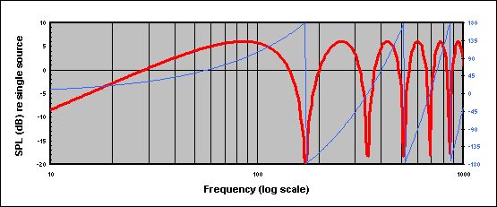
(The blue line represents the phase difference corresponding to the distance between sources.)
Looking at all this another way, the effect of the on-axis phase difference varying with frequency is that LF output rolls off at 6dB per octave. If you can afford to EQ that out (and that's a big "if"), you have a system that maintains consistent cardioid pattern control down to arbitrarily low frequency. (Directly behind the sources, the phase difference between sources is 180 degrees at every frequency and thus the only thing stopping a perfect null is level difference between the sources.)
A classic "end-fire" arrangement (all in polarity; front source delayed) gives somewhat opposite trade-offs: the response on-axis is flat, but the dispersion pattern is different at every frequency and collapses to omni at low frequency.
Predictable caveats apply: this all assumes point-source omnidirectional radiators.
Nick
Post by: Dave Rat on May 04, 2009, 02:03:57 PM
| Nick Hickman wrote on Mon, 04 May 2009 14:36 |
By "out of polarity scenario", are you describing a classic cardioid sub arrangement (rear box reverse polarity and delayed)? If so, I don't think things are as bad as you say. Having the rear source on can indeed reduce the on-axis level below that of the front source on its own but, in general, only at very low frequencies or at frequencies above the usable range of the system. The basis of this configuration is that, for an on-axis listener, the rear source arrives out of phase with the front source and this phase difference is different for every frequency. The phase difference has three components: 180 degrees from the polarity reversal, an amount that varies with frequency from the physical spacing between sources (i.e. time of flight) and, in a classic system, an equal amount from the delay applied to the rear source. Take the case where the combined front and rear sources (at equal level) give the same on-axis level as the front source only. It's easy to show that a phasor diagram must have the two sources and their resultant arranged in an equilateral triangle (i.e. all three are equal magnitude) and thus that the phase angle between the two sources must be 120 (or -120) degrees. Given the 180 degree polarity reversal, there must therefore be 30 degrees each from the physical spacing and the delay. If F is the frequency, D is the physical spacing between sources, and V is the speed of sound, we have: 30 degrees = 360 * D * F / V If D, by way of example, is 1m and V is 344m/s, then F is 28.7Hz. Below this frequency, the combined output is lower than that of a single source. There are also higher frequencies where the combined output on-axis is the same as a single source. In fact, this happens wherever the physical spacing represents either 30, 150, -30, or -150 degrees. For 1m spacing, the next occasion is at 143.3Hz and, therefore, in the region between 28.7Hz and 143.3Hz, the combined on-axis level is greater than that of a single source. Plotting far-field on-axis level against frequency for 1m source spacing looks like this (where 0dB is the level of a single source): (The blue line represents the phase difference corresponding to the distance between sources.) Looking at all this another way, the effect of the on-axis phase difference varying with frequency is that LF output rolls off at 6dB per octave. If you can afford to EQ that out (and that's a big "if"), you have a system that maintains consistent cardioid pattern control down to arbitrarily low frequency. (Directly behind the sources, the phase difference between sources is 180 degrees at every frequency and thus the only thing stopping a perfect null is level difference between the sources.) A classic "end-fire" arrangement (all in polarity; front source delayed) gives somewhat opposite trade-offs: the response on-axis is flat, but the dispersion pattern is different at every frequency and collapses to omni at low frequency. Predictable caveats apply: this all assumes point-source omnidirectional radiators. Nick |
Hello Nick,
Hey, that is exactly what I am referring to! My opinion is that though mathematically and software wise, the out of polarity delayed rear facing sub can look good, my experience is that once you start dealing with real world challenges like the rear sub firing under a stage or an engineer pounding the crap out of the subs, there are unacceptable issues that can arise. Enough issues that while that 'rear firing out of polarity setup' may be a useful tool for some applications, in that I face and for a large events in particular, I consider it to be a method I strongly avoid.
The EQ issue is not a small one. The need to add back EQ to the power-sponging low end is significant. Making the lowest frequencies even less efficient? That means carrying more amps, more speakers and increasing the size of the sub array which creates issues beyond cost, labor and truck space.
Furthermore, unless front-facing and rear-facing speakers are driven with identical EQ and power, the response of the array will change over the course of the show and and due to changes in the drive levels. Power compression, mechanical nonlinearities and protection limiters all interact to cause a myriad of complex unpredictibilities. I have experienced this first hand and the result can be dramatic. So much so that halfway through my show, the subs were louder behind the stage than in front. Not literally, but it seemed that way as the sub output significantly reduced in front and the behind the stage volume did increase. The best we could determine was that the front became less efficient due to power compression while the rear facing speakers just kept partying at full efficiency. And over the coverage flipped.
Also, since with the reverse polarity setup, the front response is dependant on the rear firing speaker, any obstructions or things like a stage that it is firing under to the rear speaker can cause the front response to be all messed up.
Conversely, the 'in-polarity' solution is for the most part 'all additive' in the coverage area and it does not require carrying extra amps and speakers for the sole purpose of cancelling sound, does not require any real change in the EQ, it is less complex to figure out and dial in and it is durable to component failures, power compression and any other common non-linearities without significantly altering the on-axis sound.
But other than that, it is all good and I highly recommend that everyone go out and get rear firing out of polarity sub setups!
Post by: Nick Hickman on May 05, 2009, 07:03:52 PM
Thanks for the comments. In your applications, I don't doubt you're making the right choices. My contribution sought to address the narrow issue of the frequency range over which the on-axis level of a pressure-gradient sub system should be greater than that of a single source.
Yes, EQing the LF rolloff flat is a big issue and constitutes a big disadvantage in applications like yours where maximum output is a priority. But there are, I think, applications where SPL needs are more modest and where the consistent pattern of the cardioid (pressure-gradient) setup is an advantage. Different trade-offs may be appropriate in different situations.
You're also right, I think, about the likelihood of a pressure-gradient system being sensitive to the acoustic environment (i.e. nearby obstructions) to a greater degree than an end-fire arrangement. And the rear null is indeed sensitive to level and EQ differences between the sources.
Nick
Post by: Dave Rat on May 05, 2009, 11:12:15 PM
| Nick Hickman wrote on Wed, 06 May 2009 00:03 |
Hi Dave, Thanks for the comments. In your applications, I don't doubt you're making the right choices. My contribution sought to address the narrow issue of the frequency range over which the on-axis level of a pressure-gradient sub system should be greater than that of a single source. Yes, EQing the LF rolloff flat is a big issue and constitutes a big disadvantage in applications like yours where maximum output is a priority. But there are, I think, applications where SPL needs are more modest and where the consistent pattern of the cardioid (pressure-gradient) setup is an advantage. Different trade-offs may be appropriate in different situations. You're also right, I think, about the likelihood of a pressure-gradient system being sensitive to the acoustic environment (i.e. nearby obstructions) to a greater degree than an end-fire arrangement. And the rear null is indeed sensitive to level and EQ differences between the sources. Nick |
Oh, and I very much agree as well. The fact that much more rejection can be realized with the reverse polarity setup and a smoother response does make it a useful tool for certain applications. Hopefully this discussion will be useful information as this subject seems an area of much misunderstanding. I personally deal primarily with large, loud or large and loud systems. I entered this thread from the angle of clarifying what was an apparent contradiction between the system design goals for Coachella's main system and the design created.
Wherein I stated a desire to avoid creating 'destructive sound' and then I went on to employ directional subs in the design. To many, it is assumed that in order to achieve a 'cardioid' pattern, an out of polarity rear facing speaker must be used to cancel sound projected to the rear (what I sloppily term 'destructive sound'). I feel the value of the 'everything in polarity and using a bit of distance and time delay' approach has been under-estimated in it's real world value. I also feel that the two approaches are more often than not lumped together, while actually they are vastly different, as you have shown an indepth knowledge of.
You brought some clear and important information to the table that I feel really helps define the difference between the two approaches, their assets, issues and hopefully allows more sound humans to chose the best tool for the job at hand.
Post by: Jens Brewer on May 06, 2009, 12:34:19 AM
| Dave Rat wrote on Mon, 04 May 2009 14:03 |
Furthermore, unless front-facing and rear-facing speakers are driven with identical EQ and power, the response of the array will change over the course of the show and and due to changes in the drive levels. Power compression, mechanical nonlinearities and protection limiters all interact to cause a myriad of complex unpredictibilities. |
Dave, I'm not sure why the response would change over the course of a show despite non equal power/eq. Once the forward facing/rear facing relationship is established (however you choose to set it), that characteristic won't change regardless of time of show, or drive level for that matter, until you push into nonlinearity. Just as the effect of a stationary boundary doesn't change over the course of an event, neither will the effect of the reversed sub in a cardioid pair. (And I assuming we're talking about deploying thoroughly tested and tweaked sub arrays from 1st tier manufacturers here, not homebrew; I'm pretty sure most of them have got their ducks straight at this point.)
That said, how many BE's chose the traditional omni sub setup vs. directional setup?
Post by: Ivan Beaver on May 06, 2009, 07:49:15 AM
| Jens Brewer wrote on Wed, 06 May 2009 00:34 |
That said, how many BE's chose the traditional omni sub setup vs. directional setup? |
Or better yet-how many know the difference and how it is done and what the consequencies are?
And the ususal answer-It depends. One size does not fit all.
Post by: Dave Rat on May 06, 2009, 01:34:11 PM
| Jens Brewer wrote on Wed, 06 May 2009 05:34 | ||
Dave, I'm not sure why the response would change over the course of a show despite non equal power/eq. Once the forward facing/rear facing relationship is established (however you choose to set it), that characteristic won't change regardless of time of show, or drive level for that matter, until you push into nonlinearity. Just as the effect of a stationary boundary doesn't change over the course of an event, neither will the effect of the reversed sub in a cardioid pair. (And I assuming we're talking about deploying thoroughly tested and tweaked sub arrays from 1st tier manufacturers here, not homebrew; I'm pretty sure most of them have got their ducks straight at this point.) That said, how many BE's chose the traditional omni sub setup vs. directional setup? |
I was not sure about that either until it happened to me several times and I was able to figure out what was occurring.
Put simply, Have you ever experienced a subwoofer system that is powerful and solid when you first start a show and then it gets softer, loses volume and impact as the show progresses? I.E. audible power compression.
Well, pretty much all speaker systems do that to some degree, just some are more apparent than others.
Well, this same thing happens with cardioid subs that have rear facing out of polarity speakers. Except, unless the rear speakers are exactly the same type, and driven with the same EQ and power levels, the power compression will tend to effect the front speakers more than the rear speakers.
Which means that the front speaker gets quieter than the processor expects it to be, over time. Or put another way, the rear speaker is now disproportionately too loud in relation to the front. Hence, louder behind, quieter in front.
So, unlike a conventional sub setup and 'in polarity sub setups' where power compression effects overall level and sound in a fairly uniform way. The reverse polarity rear fire sub setup will tend to become unstable in its coverage pattern when driven hard.
The assumption that 1st tier manufacturers will actually only release products that have a lack of complex and significant issues, is about as reliable as assuming 1st tier software companies will not release software with bugs.
I have been exposed to numerous system unveiling's from top manufacturers and they rely on us guys in the field to point out the issues. Many of these designs look good on paper but are seriously flawed in real world applications, even from the top companies.
I think a more useful assumption is that most manufacturers will test things at lower volumes, in smaller setups for shorter periods of times that the products will actually experience.
Post by: Phillip_Graham on May 06, 2009, 02:41:09 PM
I have kept on the sidelines for a few pages on thread, and I appreciate you continuing to discuss the topic, but I fear there is some imprecise physics being bandied about here.
There is not really such thing as "anti-sound" sound is sound. Whether it be an endfire or cardioid configuration, all of the energy the loudspeakers put out is conserved, and appears somewhere in the directivity lobe around the system. The integrated flux of energy through a sphere, or hemisphere, around the system is conserved. Now that some of that energy may be dissipated as heat, but it did not disappear. Dr. Vanderkooy did the derivation of the heat increase inside of a sealed box at his master class at the September AES in San Fran.
I don't think that you me to infer that energy vanishes, but I think the casual reader might draw that conclusion.
| Quote: |
Put simply, Have you ever experienced a subwoofer system that is powerful and solid when you first start a show and then it gets softer, loses volume and impact as the show progresses? I.E. audible power compression. |
Definitely! Of course sometimes its hard to discern how much of that compression is the PA, and how much is the natural compression of the muscles in one's ears.
| Quote: |
Well, this same thing happens with cardioid subs that have rear facing out of polarity speakers. Except, unless the rear speakers are exactly the same type, and driven with the same EQ and power levels, the power compression will tend to effect the front speakers more than the rear speakers. |
A valid reason to not attenuate the rear speaker, but rather use multiple front cabinets, so the input levels are the same. Of course if we are going to get really subtle, the forward and reverse loudspeakers are going to experience different local radiation impedances, which is going to affect their tuning slightly.
In general I have only made cardioid arrays out of identical cabinets, and the only processing variations between the boxes are in the time domain (delay and allpasses), and don't make front and rear amplitude variations.
| Quote: |
So, unlike a conventional sub setup and 'in polarity sub setups' where power compression effects overall level and sound in a fairly uniform way. The reverse polarity rear fire sub setup will tend to become unstable in its coverage pattern when driven hard. |
I am curious why you feel the endfire situation provides any advantage here? After all, if the cardiod array is using the same type box driven at the same levels with only delay and a polarity inversion, where is the differential response on the rear speaker coming from?
PS As a point intention, let me state publicly that I think the endfire-type arrays subjectively sound a little better than cardioid, so I am not really opposing what you have done in practice, but trying to make sure the physics remains lucid.
Post by: Dave Rat on May 06, 2009, 06:29:26 PM
| Phillip Graham wrote on Wed, 06 May 2009 19:41 |
Dave, I have kept on the sidelines for a few pages on thread, and I appreciate you continuing to discuss the topic, but I fear there is some imprecise physics being bandied about here. There is not really such thing as "anti-sound" sound is sound. Whether it be an endfire or cardioid configuration, all of the energy the loudspeakers put out is conserved, and appears somewhere in the directivity lobe around the system. The integrated flux of energy through a sphere, or hemisphere, around the system is conserved. Now that some of that energy may be dissipated as heat, but it did not disappear. Dr. Vanderkooy did the derivation of the heat increase inside of a sealed box at his master class at the September AES in San Fran. I don't think that you me to infer that energy vanishes, but I think the casual reader might draw that conclusion. I am curious why you feel the endfire situation provides any advantage here? After all, if the cardiod array is using the same type box driven at the same levels with only delay and a polarity inversion, where is the differential response on the rear speaker coming from? PS As a point intention, let me state publicly that I think the endfire-type arrays subjectively sound a little better than cardioid, so I am not really opposing what you have done in practice, but trying to make sure the physics remains lucid. |
I do not think there is any disagreements here. Of course there is no 'anti sound.'
You can define the differential between the method I support and the one I avoid. Simplistically put I find that for the application at hand the designs that:
If you turn up the front speakers it should get louder in front. (and louder to the rear is ok too).
If you then turn up the speakers facing rearward it should get even louder in front and quieter to the rear. Pattern control is realized while also increasing volume radiated in the forward coverage area.
I avoid systems that:
If you turn on the front speakers it gets louder in front.
If you then turn up the rear speakers it gets quieter in front(and quieter in the rear). Though pattern control is realized but at the expense of suffering a reduced volume level in the forward coverage area.
Does that 'additive versus subtractive result in the forward field' concept not make sense?
Post by: Ivan Beaver on May 06, 2009, 07:36:06 PM
| Dave Rat wrote on Wed, 06 May 2009 18:29 |
If you turn on the front speakers it gets louder in front. If you then turn up the rear speakers it gets quieter in front(and quieter in the rear). Though pattern control is realized but at the expense of suffering a reduced volume level in the forward coverage area. |
I have never seen (or heard of) a system that will get quieter in front when the rear loudspeakers are turned on. I would suspect that either it is some arrangement other than what is being talked about-or else it was deployed wrong-which is more likely the case. Probably by people who did not understand the concept and how it works.
Don't blame the system/technology if it is set up wrong.
Both endfire and cardoiod systems are lower in level on axis than with the same number of boxes all piled up in a front firing arrangement. But you will get some addition out front (and lots of reduction in the rear) when the rear boxes are turned on (properly
Post by: Phillip_Graham on May 06, 2009, 07:49:47 PM
| Dave Rat wrote on Wed, 06 May 2009 18:29 |
Does that 'additive versus subtractive result in the forward field' concept not make sense? |
I feel this is a relative tradeoff, and we are of course talking about the far field behavior where the relative level of the front and back boxes is essentially the same.
The endfire config might be 2dB up in the axial position of the forward lobe relative to the cardioid, but that has come at change in shape of the main lobe, and impaired directivity behind the array.
Both endfire and cardioid are well ahead of a traditional array for the same number of boxes due to their substantially higher forward directivity, and the attendant reduction of energy that was previously wasted on areas where there was no audience.
Don't let the apparent level at the center of the axial forward array trick you into thinking that somehow that energy doesn't come back out somewhere else in the coverage pattern.
And, again, the configuration method you suggest subjectively sounds a little better to me in the nearfield.
This is probably generating more heat than light at this point, so I will bow out, as this seems a good thread and I would rather not get dragged down on one point.
[Edit: removed "in output" for clarity]
Post by: Peter Morris on May 07, 2009, 02:05:24 AM
“Both endfire and cardioid are well ahead of a traditional array in output for the same number of boxes due to their substantially higher forward directivity, and the attendant reduction of energy that was previously wasted on areas where there was no audience.”
Ivan said:-
“Both endfire and cardoiod systems are lower in level on axis than with the same number of boxes all piled up in a front firing arrangement. But you will get some addition out front (and lots of reduction in the rear) when the rear boxes are turned on (properly
Hi Phil,
This is an old discussion for you and me, but I have to agree with Ivan.
Cardioid systems sum in front, cancel at the rear and energy is conserved, but the sound energy from the rear is not transferred as extra sound energy out front, it’s (more or less) lost in heat….sooo they will have the same forward (slight less) output compared to the same number of boxes (front + back) in a traditional array.
Then there is my issue of adding two identical non symmetrical acoustic waveforms together – one of which is delayed by approximately 1/2; the period of the dominant frequency and inverted before it’s added to the other……. The resultant wave form’s shape and length is not the same as the original unless it’s a pure continuous tone.
A cardioid sub maybe a very useful compromise, but it comes at a price. To my ear the price is loosing a bit of that “tight punch” compared to the original.
Having said that, the gain from reducing the amount of rear energy and the issues associated with this energy may more than offset any loss.
Regards
Peter
Post by: Nick Hickman on May 07, 2009, 08:12:34 AM
| Phillip Graham wrote on Thu, 07 May 2009 00:49 |
Both endfire and cardioid are well ahead of a traditional array in output for the same number of boxes due to their substantially higher forward directivity, and the attendant reduction of energy that was previously wasted on areas where there was no audience. |
Taken literally, I don't think that can be correct.
Take, for example, a pressure-gradient (cardioid) array with the sources 1m apart. At 20Hz, the uncorrected output on-axis (in a simple model) is -3dB relative to the output of a single source, and it's less everywhere else. Averaged over space, it's about -7dB relative to a single source. In contrast, a tight-packed "traditional array" of two sources would be almost +6dB everywhere.
From a conservation of energy perspective, I understand this to be mutual coupling in reverse. When the spacing of the sources is small with respect to wavelength (i.e. at low frequency), the two out-of-polarity sources act on each other to reduce the radiation resistance with the result that little energy is delivered to the air.
Interested in your thoughts.
Nick
Post by: Nick Hickman on May 07, 2009, 09:02:18 AM
| Peter Morris wrote on Thu, 07 May 2009 07:05 |
Cardioid systems sum in front, cancel at the rear and energy is conserved, but the sound energy from the rear is not transferred as extra sound energy out front, it’s (more or less) lost in heat….sooo they will have the same forward (slight less) output compared to the same number of boxes (front + back) in a traditional array. |
I don't think energy is "lost in heat" (except in the sense of that being its ultimate fate). Any energy radiated goes somewhere, and any spaced arrangement of sources will create a dispersion pattern that puts more energy in one direction and less in another.
| Quote: |
Then there is my issue of adding two identical non symmetrical acoustic waveforms together – one of which is delayed by approximately 1/2; the period of the dominant frequency and inverted before it’s added to the other……. The resultant wave form’s shape and length is not the same as the original unless it’s a pure continuous tone. |
I'm not entirely sure what you mean, but any time-domain disruption (such as a second arrival) will have an impact in the frequency-domain. Remember that the systems under discussion are only addressing a narrow band of low frequencies so be sure to band-pass your thought experiments!
Nick
Post by: SteveKirby on May 07, 2009, 01:46:35 PM
I think this is why Dave calls this a subtractive or lossy process. It takes additional energy to subtract the rearward radiation. And none of that energy contributes to the foward radiation.
Agreed that a more controlled foward radiation pattern does allow you to put more energy where you want it without wasting it where you don't (in an ideal world where the boxes do exactly what they're theoretically capable of without interference from stages, punters or anything else). Like a narrow pattern horn sounds louder in the more limited area of it's coverage. But I don't understand how it creates additional energy out of thin air.
Post by: Phillip_Graham on May 07, 2009, 01:55:27 PM
| Peter Morris wrote on Thu, 07 May 2009 02:05 |
Phil said:- “Both endfire and cardioid are well ahead of a traditional array in output for the same number of boxes due to their substantially higher forward directivity, and the attendant reduction of energy that was previously wasted on areas where there was no audience.” Ivan said:- “Both endfire and cardoiod systems are lower in level on axis than with the same number of boxes all piled up in a front firing arrangement. But you will get some addition out front (and lots of reduction in the rear) when the rear boxes are turned on (properly Hi Phil, This is an old discussion for you and me, but I have to agree with Ivan. Cardioid systems sum in front, cancel at the rear and energy is conserved, but the sound energy from the rear is not transferred as extra sound energy out front, it’s (more or less) lost in heat….sooo they will have the same forward (slight less) output compared to the same number of boxes (front + back) in a traditional array. |
Peter,
Let me be clear that I Do NOT disagree with Ivan, but I am guilty of not being clear above, as I reread it.
I didn't say anything about the acoustic output of the cardioid array, but I can see how it reads like I did.
For clarity:
1. If you have two coherent sources they provide you 6dB of gain (like identical channels on a mixing board).
2. If you have two spaced sources they can sum by as much as +6dB or -infinity, depending on the phasor relationship. The maximum case of +6dB is the same as the coherent source case, you can't do better than that.
3. The average power of the integrated combination of the spaced sources in #2 is +3dB of gain.
4. This gives the closely spaced coherent sources at +3dB gain relative to the spaced sources (i.e. the cardioid OR ENDFIRE cases)
Ivan and I agree here, and this wasn't what I meant to be talking about.
The advantage I was trying to espouse by saying "well ahead" is the behavior of the excited reverberant field in the space. The coherent source drives the reverberant field harder than the source with controlled directivity, and herein lies the advantage. Meaning the source with controlled directivity adds less energy into the reverberant field, and this is of more practical sonic benefit than a simple 3dB of total output.
| I said |
the attendant reduction of energy that was previously wasted on areas where there was no audience.” |
I didn't say anything about increased subwoofer output, rather only the reduction of energy dumped into places where it does not need to go (i.e. the reverberant field).
The two closely spaced sources represent the best-case for coherent addition, and the controlled directivity arrays are not going to supersede this case. What they will do, however, is improve the reverberant field behavior, which gives them an advantage in practical physical spaces.
Does this clear it up?
[Edit: Clarity per Art Welter's PM suggestion. Edit in italics]
Post by: Phillip_Graham on May 07, 2009, 02:00:38 PM
| Nick Hickman wrote on Thu, 07 May 2009 08:12 | ||
Hi Phil,
Taken literally, I don't think that can be correct. {snip} Interested in your thoughts. Nick |
Nick,
Please see my reply to Peter Morris (one post above in flat view).
That should clarify where I was coming from. The system result is "well ahead" not because of an increase in output relative to a close-coupled source pair, but rather due to an improvement in the behavior of the reverberant field.
Since LF problems, in my experience, are 99%+ dominated by the physical room, dumping less energy into the reverberant field of the room is of universal practical advantage.
Post by: Tim McCulloch on May 07, 2009, 03:41:13 PM
But there's been more brain food in this thread than anything posted in the last couple of months (maybe longer).
Very good stuff to make one think...
Have fun, good luck.
Tim Mc
Post by: Matt Donarski on May 07, 2009, 06:37:01 PM
| Nick Hickman wrote on Thu, 07 May 2009 08:02 | ||
I don't think energy is "lost in heat" (except in the sense of that being its ultimate fate). Any energy radiated goes somewhere, and any spaced arrangement of sources will create a dispersion pattern that puts more energy in one direction and less in another. |
Actually for two close spaced sources where spacing << wavelength and one is inverted polarity energy is 'lost as heat' in a sense. Energy is never created or destroyed. What happens is the radiation impedance of each source is affected by the other and the net efficiency of the system is reduced to ~0. The energy is not actually lost it is just not transfered into the acoustic domain. The power transfered to such a system is dissapated by electrical and mechanical resistive elements as heat.
-Matt
Post by: Ivan Beaver on May 07, 2009, 06:44:33 PM
| Phillip Graham wrote on Thu, 07 May 2009 14:00 |
That should clarify where I was coming from. The system result is "well ahead" not because of an increase in output relative to a close-coupled source pair, but rather due to an improvement in the behavior of the reverberant field. Since LF problems, in my experience, are 99%+ dominated by the physical room, dumping less energy into the reverberant field of the room is of universal practical advantage. |
Agreed. Signal to noise ratios (wanted sub energy vs unwanted room energy driven by the subs) are not always best fixed by more signal. But very often by reducing the "noise" (unwanted signal of any tyep). Gain structure 101. Directional Sub idea 101.
Post by: Peter Morris on May 08, 2009, 01:59:14 AM
I was trying to keep the description and terminology simple, but I’m sure Matt’s correct in that the energy is also dissipated in the mechanical and electrical components as a result of changes to the radiation impedance.
@ Phil – I read your post about 10 times just to make sure …. so I’m glade to see its not just me that’s guilty of being unclear from time to time…
@ Nick – that last bit of my post is about the rear sub being time delayed and inverted and what happens at the front of the array. (guilty as above)
When I have time what I want to do is apply a drum beat pulse to two inputs of a digital crossover with a 30 to 80 Hz pass band – invert and delay one output channel by 8ms then add those two signal together.
Then I want to graphically compare the result with the original signal (+6dB) over the same pass band on an oscilloscope or similar. I’m sure you could do it with mathcad (if I had a copy)
Peter
Post by: Evan Kirkendall on May 08, 2009, 02:04:35 AM
| Tim McCulloch wrote on Thu, 07 May 2009 15:41 |
Subject line says it all... But there's been more brain food in this thread than anything posted in the last couple of months (maybe longer). Very good stuff to make one think... Have fun, good luck. Tim Mc |
+1. One of the most informative threads I've seen on here in a long time! I've forwarded this whole thread to the system techs on this tour just for some good reading.
Evan
Post by: Ivan Beaver on May 08, 2009, 08:00:44 AM
| Peter Morris wrote on Fri, 08 May 2009 01:59 |
When I have time what I want to do is apply a drum beat pulse to two inputs of a digital crossover with a 30 to 80 Hz pass band – invert and delay one output channel by 8ms then add those two signal together. Then I want to graphically compare the result with the original signal (+6dB) over the same pass band on an oscilloscope or similar. I’m sure you could do it with mathcad (if I had a copy) Peter |
Not the same thing. It is the COMBINATION of physical distance (time of flight) AND (electronic) delay, AND/OR NOT polarity inversion (depending on what type alignment you are trying to do), that makes it work-not just one or two of those.
If all you do is delay a signal (and flip the polarity (or not-a DSP has no way of knowing if one output is in front of the other) and mix it with a non delayed signal, you will just get classic combfiltering.
There is really no reason to waste your time. Because the results are NOT at all what happens in the real world.
Post by: Peter Morris on May 08, 2009, 09:49:02 AM
| Ivan Beaver wrote on Fri, 08 May 2009 13:00 | ||
Not the same thing. It is the COMBINATION of physical distance (time of flight) AND (electronic) delay, AND/OR NOT polarity inversion (depending on what type alignment you are trying to do), that makes it work-not just one or two of those. If all you do is delay a signal (and flip the polarity (or not-a DSP has no way of knowing if one output is in front of the other) and mix it with a non delayed signal, you will just get classic combfiltering. There is really no reason to waste your time. Because the results are NOT at all what happens in the real world. |
It is the same ... 4 ms of physical distance plus the digital delay ....thats why I said 8 ms ...do the math - make a mathematical model of it....
Regards
Peter
Post by: Nick Hickman on May 08, 2009, 11:52:17 AM
| Peter Morris wrote on Fri, 08 May 2009 06:59 |
@ Nick and Matt – I did say that energy was conserved …and … I was talking about sound energy being (more or less) lost in heat. I was trying to keep the description and terminology simple, but I’m sure Matt’s correct in that the energy is also dissipated in the mechanical and electrical components as a result of changes to the radiation impedance. |
My understanding runs like this... Electrical energy is always converted to heat in the electrical and mechanical resistive elements of the loudspeaker. What we're interested in here is the radiation resistance which is the part of the load that transfers energy to the air. In the case of two closely-spaced (with respect to wavelength) sources in opposite polarity, the radiation resistance drops very low so very little energy is transferred to the air. No extra energy is lost as heat (and that was my point before). The radiation resistance is usually a very small part of the total load seen by the amplifier, so the effect on the overall load is small.
If the two closely-spaced sources were in polarity rather than out of polarity, the radiation resistance would be doubled relative to a single source and, because the system acts like a constant current source, the power transferred to the air would also be doubled. This is "mutual coupling".
| Quote: |
@ Nick – that last bit of my post is about the rear sub being time delayed and inverted and what happens at the front of the array. (guilty as above) When I have time what I want to do is apply a drum beat pulse to two inputs of a digital crossover with a 30 to 80 Hz pass band – invert and delay one output channel by 8ms then add those two signal together. Then I want to graphically compare the result with the original signal (+6dB) over the same pass band on an oscilloscope or similar. I’m sure you could do it with mathcad (if I had a copy) |
Okay, so you're simulating a cardioid sub on axis?
Two things: First, 8ms is a bit long; it implies a source spacing of 1.4m which puts the transition frequency for a cardioid sub at 62Hz. Second, if you do only what you said, you'll see a gross change in the waveform. This is equivalent to using the cardioid system uncorrected (see the frequency response plot I posted earlier in the thread). You need to apply corrective EQ (roughly a 6dB per octave LPF) just as would be done with a real system.
Rather than use hardware, you could do it in a wave editor program. For example, I took this kick drum hit, filtered it (30Hz HP, 80Hz LP, 24dB/oct) to give this, then added an inverted delayed copy to give this, and then applied a 6dB/oct LPF to give this. The filtered and "cardioid processed" versions overlaid (slightly offset vertically) look like this:
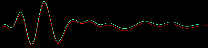
Nick
Post by: Andrew Welker on May 08, 2009, 11:53:23 AM
Post by: Joseph Curran on May 08, 2009, 12:02:25 PM
| Andrew Welker wrote on Fri, 08 May 2009 16:53 |
Its not just the delay, its the physical placement of the cabinets as well. If you don't have the rear cabinet directly behind the front cabinet, no matter what you do with delay, polarity, or eq you won't get the pattern control you are looking for. |
This was my understanding as well.
Post by: Phillip_Graham on May 08, 2009, 12:24:07 PM
| Andrew Welker wrote on Fri, 08 May 2009 11:53 |
Its not just the delay, its the physical placement of the cabinets as well. If you don't have the rear cabinet directly behind the front cabinet, no matter what you do with delay, polarity, or eq you won't get the pattern control you are looking for. |
Nick's simulation is a 1d case, it is equivalent to the on-axis, farfield response of a cardioid subwoofer array operating in infinite free space as picked up by an omnidirectional microphone, and is thus suitable for demonstration of concepts here.
Nick,
I think it would be instructive to show the same result two other ways:
1. Without the 6dB LPF (bc many people don not run this in their cardioid implementations).
2. With an allpass filter that mirrors the phase reponse, but not magnitude response, of the 6dB LPF.
Post by: Tom Danley on May 08, 2009, 01:37:34 PM
Here is a fun applet that may be useful here.
In many ways, an array of antenna’s is much like an array of subwoofers or acoustically small sources.
To visualize what Ivan was hearing, set the sources to 9 (the maximum), set the distance between each source to say 3 (3/10 wl) and phase to zero.
To make a universal directive array, set the number of sources to two, set the spacing to 2 or 3 tenths of a wl, set the phase to about 90 degrees.
Keep in mind, one uses a time delay to cause the 90 degree phase shift in loudspeaker world.
Funny thing about this arrangement, at this spacing, flipping the drive on one box, or switching which is delayed, only reverses the polar pattern. Other than that, there is no difference between in phase (end fire) and out of phase (card) array.
In both cases, the total radiated energy is less than that radiated by both sources if they were in phase less than a quarter wl apart while the on axis SPL is about the same
Anyway, I thought this might be fun so give it a shot.
http://www.qsl.net/rast/text/antenna.html
Best,
Tom Danley
Post by: Sebastiaan Meijer on May 08, 2009, 06:40:27 PM
To add even more to the confusion and mind breakers:
The applet, and so does about every cardoid solution, assumes that we are dealing with sine waves. The 'back speaker' is delayed (both physically and electronically most often) and therefore can only sum to the front when the second period of the wave is identical to the first one. (Or when using polarity reversal: when the second half of the sine wave is identical but opposite of the first half). Now the question is whether this is a valid assumption for live music. In my experience this is not, thus my preference for the (more) impulse-correct end-fired solution.
Another thing to add in this: how do the cabs in front load the cabs in the back by their physical properties? I simply don't know, but have experienced the impact of not even densily packed people near a sub stack. It got me thinking.....
Best regards,
Sebas
Post by: Peter Morris on May 08, 2009, 07:58:10 PM
| Sebastiaan Meijer wrote on Fri, 08 May 2009 23:40 |
Hi Tom, To add even more to the confusion and mind breakers: The applet, and so does about every cardoid solution, assumes that we are dealing with sine waves. The 'back speaker' is delayed (both physically and electronically most often) and therefore can only sum to the front when the second period of the wave is identical to the first one. (Or when using polarity reversal: when the second half of the sine wave is identical but opposite of the first half). Now the question is whether this is a valid assumption for live music. In my experience this is not, thus my preference for the (more) impulse-correct end-fired solution. Another thing to add in this: how do the cabs in front load the cabs in the back by their physical properties? I simply don't know, but have experienced the impact of not even densily packed people near a sub stack. It got me thinking..... Best regards, Sebas |
Hi Sebas
EXACTLY !!!! Everyone assumes we are talking about continuous sin waves, and on those wave forms it works. Music is not, the wave forms are asymmetric and impulsive.
Perhaps if you consider a signal that makes the front speakers cone more forward (only) from 'zero' and back to 'zero' once……… the rear speaker is inverted so its cone moves backward (after the time delay) and then back to zero.
What get out front is a +ve pressure followed by a –ve pressure. The original wave form was just one +ve pulse and 8 ms shorter (4 ms delay + 4ms from position)
Peter
Post by: Lee Brenkman on May 08, 2009, 08:22:10 PM
BUT to give you all a look into the way MY brain is wired...
When I saw the original thread title, "Amazing bass and Evan's gig" I overlooked the apostrophe and immediately thought of:
The amazing bass player Eddie Gomez with the Bill Evans Trio.
Shows my age, musical experiences and orientation.
Cheers,
Grampa
Post by: Ivan Beaver on May 08, 2009, 08:27:26 PM
Funny thing is that they were called upright basses-before there was the "horizontal" (electric) bass. So what was the "other type" back then?
Post by: Mac Kerr on May 08, 2009, 08:36:07 PM
| Ivan Beaver wrote on Fri, 08 May 2009 20:27 |
Wouldn't that be "Amazing UPRIGHT bass"? Funny thing is that they were called upright basses-before there was the "horizontal" (electric) bass. So what was the "other type" back then? |
Were they? Or were they just called basses, or bass viols? Even a cello, or viola de Gamba is "upright", you just sit down to play them. I've never seen a label on an orchestra plot for "upright bass" just "bass". When did the guitarron first appear?
Mac
Post by: Phillip_Graham on May 08, 2009, 08:43:59 PM
| Peter Morris wrote on Fri, 08 May 2009 19:58 |
EXACTLY !!!! Everyone assumes we are talking about continuous sin waves, and on those wave forms it works. Music is not, the wave forms are asymmetric and impulsive. Perhaps if you consider a signal that makes the front speakers cone more forward (only) from 'zero' and back to 'zero' once……… the rear speaker is inverted so its cone moves backward (after the time delay) and then back to zero. What get out front is a +ve pressure followed by a –ve pressure. The original wave form was just one +ve pulse and 8 ms shorter (4 ms delay + 4ms from position) Peter |
Peter,
This is bad physics and you (should?) know it. There is nothing wrong with not liking a cardioid subwoofer, but don't use bad physics to justify that dislike. I know you know the physics, so I respond to you and not the other poster.
1. Any LTI signal can be represented as the sum of periodic functions, e.g sine functions. This is a critical basic from Fourier analysis, and something I am sure you aren't arguing.
2. A wave has no meaning until you define the complete period. You cannot speak about an 100Hz tone until you have defined enough time for one period (10ms), because the signal is not periodic until it repeats. Thus the superposition of the acoustic pressure has to be considered on the timescale of the underlying wave period.
3.
| your thought experiment |
Perhaps if you consider a signal that makes the front speakers cone more forward (only) from 'zero' and back to 'zero' once……… the rear speaker is inverted so its cone moves backward (after the time delay) and then back to zero. |
In your example you are speaking of system with arbitrary start and stop points. A system that completes one period only and stops instantaneously. First that is not a physical reality, by consequences of the differential nature of newton's third law.
Even if your hypothetical system came to rest in such a way, Fourier analysis requires many other frequency components at the trailing and/or leading edge. Because that hypothetical system, by definition, requires higher frequency components to start and stop the signal, it must violate the wavelength spacing requirements cardioid array for these other frequencies.
Even if you were to excite the system with a delta function or a square wave, the thought experiment ignore the removal of these higher frequency components from the signal fed the array by the lowpass filter.
4. The group delay of this system is already severely affected by both the combined phase response of the high and lowpass filters on the subwoofer, plus the acoustic phase due to the box tuning, so it is overstated to act as if the cardioid is the only thing causing these problems. The single box case already has time domain effects from the non-cardioid processing.
--
Vitriol aside, please see that I am not saying this case, and the endfire case are equivalent. Indeed, I AGREE 100% with the improvement the endfire shows relative to the cardioid case. I do not agree with the misappropriation of physics to do so.
For the endfire case, the delayed front cabinet is in phase with the rear cabinet on the audience side of the array, but not so with the cardioid array.
Post by: Lee Brenkman on May 08, 2009, 08:53:51 PM
The double bass originally doubled the bass part an octave lower.
Sort of a bowed string subwoofer :-0!
See! I guess this wasn't as far off the topic of the thread as I thought.
And Eddie played a full size bass, not a 7/8 or 3/4 sized one like most jazz players.
Post by: Sebastiaan Meijer on May 08, 2009, 09:44:37 PM
| Phillip Graham wrote on Sat, 09 May 2009 02:43 | ||
Peter, This is bad physics and you (should?) know it. There is nothing wrong with not liking a cardioid subwoofer, but don't use bad physics to justify that dislike. I know you know the physics, so I respond to you and not the other poster. |
Philip,
While your snarky reply is quite rude in terms of addressing me, I will try to reply. No, I am not an official physics scientist, but starting with several years in engineering at university gave me some background, and the research done here in our audio lab provides some too. I choose a doctorate in another field however.
| Quote: |
1. Any LTI signal can be represented as the sum of periodic functions, e.g sine functions. This is a critical basic from Fourier analysis, and something I am sure you aren't arguing. |
Yes, this is the basis of audio measurements.
| Quote: |
2. A wave has no meaning until you define the complete period. You cannot speak about an 100Hz tone until you have defined enough time for one period (10ms), because the signal is not periodic until it repeats. Thus the superposition of the acoustic pressure has to be considered on the timescale of the underlying wave period. |
Yes, true too. However, at a certain moment a signal will stop. And then you should not forget that there are 2 acoustic sources.
| Quote: |
3. Perhaps if you consider a signal that makes the front speakers cone more forward (only) from 'zero' and back to 'zero' once……… the rear speaker is inverted so its cone moves backward (after the time delay) and then back to zero. |
In your example you are speaking of system with arbitrary start and stop points. A system that completes one period only and stops instantaneously. First that is not a physical reality, by consequences of the differential nature of newton's third law.
[/quote]
The system has to stop at some moment, and of course this cannot be instantaneously. But at least the speaker slows down significantly.
| Quote: |
Even if your hypothetical system came to rest in such a way, Fourier analysis requires many other frequency components at the trailing and/or leading edge. Because that hypothetical system, by definition, requires higher frequency components to start and stop the signal, it must violate the wavelength spacing requirements cardioid array for these other frequencies. Even if you were to excite the system with a delta function or a square wave, the thought experiment ignore the removal of these higher frequency components from the signal fed the array by the lowpass filter. |
So, now let me provide an example:
The front and the back speaker each are fed with a 100Hz continuous sine wave. Now at time T1 we suddenly stop the signal generator, precisely at 0V. The front speaker is exactly in the most forward position, with speed = 0, and the back speaker is at the most inwards position, with speed = 0. Now we are going to listen at a position on axis of the cardiod array where the sine wave sums perfectly. What are we going to hear when the signal generator is stopped? First we hear the HF content arriving from the front speaker associated with the sudden voltage drop at the voice coil, combined with the 100Hz that is still on its way from the back speaker. After the combination of electric and acoustic delay (lets say, 2.5 + 2.5 ms) we hear the HF content from the rear speaker arriving.
Now I realise that I should not have said: "This model assumes sine waves" but should have been more explicit to say "This model assumes CONTINUOUS sine waves". Music however is something that starts and stops various frequencies by definition. This does not deny physics but puts constraints to where to apply which model.
| Quote: |
4. The group delay of this system is already severely affected by both the combined phase response of the high and lowpass filters on the subwoofer, plus the acoustic phase due to the box tuning, so it is overstated to act as if the cardioid is the only thing causing these problems. The single box case already has time domain effects from the non-cardioid processing. |
Yes, but this is not different from any other processed box. What the cardiod thing adds to this is multiple arrival times of the identical signal, which is a problem with non-continous sines / signals called music. Hence the nice rolling electro and dance lows you get with the cardiod solutions but rarely a good kick drum or acoustic bass.
| Quote: |
-- Vitriol aside, please see that I am not saying this case, and the endfire case are equivalent. Indeed, I AGREE 100% with the improvement the endfire shows relative to the cardioid case. I do not agree with the misappropriation of physics to do so. For the endfire case, the delayed front cabinet is in phase with the rear cabinet on the audience side of the array, but not so with the cardioid array. |
As long as we agree on the outcome
Sebas
Post by: Peter Morris on May 08, 2009, 10:49:43 PM
I will simplify it a little more-
Front speaker - let’s assume percussive signal of 100ms in length, the bit that has been LP filter at 80Hz.
Rear speaker 4 ft behind it is delayed and inverted by 4ms with the same signal.
Stand 10 feet or 10ms (approx) in front of the front speaker and listen.
At time = 10ms you start to hear the front speaker
At time = 18 ms you start to hear both speakers, or I should say the sum of the two.
At time = 110ms you stop hearing the front speaker
At time = 118 ms you stop hearing the rear speaker
Sooo that bass signal that was 100 ms is now 108ms long
Regards
Peter
Post by: Phillip_Graham on May 08, 2009, 11:58:04 PM
| Sebastiaan Meijer wrote on Fri, 08 May 2009 21:44 |
While your snarky reply is quite rude in terms of addressing me, I will try to reply. No, I am not an official physics scientist, but starting with several years in engineering at university gave me some background, and the research done here in our audio lab provides some too. I choose a doctorate in another field however. |
It is unfortunate that my words came off as snarky, I do apologize. In this case I truly meant what I wrote in a literal sense. I have conversed with Peter for years outside this forum, which he even alluded to earlier in this thread, and have first hand knowledge of his expertise with loudspeaker physics.
I remember you having been a more frequent poster in the distant past, but not so much recently, and if my brain remembers right you have a terminal degree in psychology? I remember using a reverb trick you posted once. I really didn't know anything about your physics background, hence I decided to jump on the guy I knew for sure should know better...
| Sebas Replies: | ||
Yes, true too. However, at a certain moment a signal will stop. And then you should not forget that there are 2 acoustic sources. |
More accurately the signal will decay, over time by the way its envelope function is manipulated by the electrical filter bandpass, and then the loudspeaker system.
| Quote: |
So, now let me provide an example: The front and the back speaker each are fed with a 100Hz continuous sine wave. Now at time T1 we suddenly stop the signal generator, precisely at 0V. The front speaker is exactly in the most forward position, with speed = 0, and the back speaker is at the most inwards position, with speed = 0. Now we are going to listen at a position on axis of the cardiod array where the sine wave sums perfectly. What are we going to hear when the signal generator is stopped? First we hear the HF content arriving from the front speaker associated with the sudden voltage drop at the voice coil, combined with the 100Hz that is still on its way from the back speaker. After the combination of electric and acoustic delay (lets say, 2.5 + 2.5 ms) we hear the HF content from the rear speaker arriving. |
So far I am not disagreeing with this thought experiment, but I would point out to rapidly stop the system in the manner which you suggest requires removal the electronic bandpass filter (ie LP+HP) before the subwoofer. The system is now producing a much wider bandwidth of frequencies, the majority of which are not at the required physical dimensions for the cardioid case posited.
| Quote: |
Now I realise that I should not have said: "This model assumes sine waves" but should have been more explicit to say "This model assumes CONTINUOUS sine waves". |
A sine wave, by mathematical definition is continuous. The moment the sine wave becomes an envelope function it can be decomposed into a summation of other sine components. This is most of the essence of Fourier's work.
Fourier analysis separates out the components, looks at their respective amplitude and phase, and then sums (integrates) all the frequency terms to describe the original signal. By considering only one frequency as an example, we make the concepts at hand more visually palpable, and the superposition of the individual frequency components makes the principals general.
| Quote: |
Music however is something that starts and stops various frequencies by definition. This does not deny physics but puts constraints to where to apply which model. |
The frequency content that passes through the subwoofer bandpass is bandpassed. This will define the behavior of the envelope to an arbitrary function. When music is passed through the filter set, it changes the frequency and phase content that remains at the output.
Mathematically we can consider this a convolution. If one measures the impulse response of the bandpass filter set f(t), and then performs convolution with the input function, ie music, g(t) by that impulse response, one gets the time domain output of the LTI system.
Then by the convolution theorem, this action is equivalent of the pointwise multiplication of the Fourier Transform of the two functions. f(t)*g(t) is equivalent to FT(f(t)) x FT(g(t)). This relatively simple mathematical statement has profound implications in physics and DSP.
The time and frequency domains are intractably linked. The limited frequency bandwidth imposed by the high and lowpass filters defines boundaries to the "rapidity" of the behavior of the physical system, and we are only considering the behavior of a specific bandpass and a specific, fixed, physical spacing between sources.
| Quote: |
Yes, but this is not different from any other processed box. What the cardiod thing adds to this is multiple arrival times of the identical signal, which is a problem with non-continous sines / signals called music. Hence the nice rolling electro and dance lows you get with the cardiod solutions but rarely a good kick drum or acoustic bass. |
Let me try this explanation again, with more detail and clarity, in case we are talking past each other:
We stand on a large flat plane with a cardioid sub array well away from us, directly on axis in front of the array. A signal comes to the cardioid array. This signal is no longer a pure sine wave, but rather an envelope function defined by the corner frequency of a hypothetical brickwall low pass filter. For the sake of ease, let us say that corner is at 100Hz. The the highest frequency our envelope can track is also 100Hz, plus the sum of whatever frequencies also lie in the subwoofer bandpass. This defines the minimum allowed period of our envelope function to be 10 milliseconds.
Now, the envelope begins to leave the front subwoofer at time zero. For simplicity's sake the inter-box spacing is 1/4 wavelength at 100Hz, and the inter box delay is the same. In physical delay time that represents 10ms/4=2.5ms of physical propagation delay, plus 2.5ms of processor induced delay.
Thus the inverted polarity envelope function from the rear subwoofer begins arriving at the front box 5 milliseconds after the normal polarity envelope function. Now this is where the mind has to become flexible.
Because of the bandpass filter in play, the minimum period of our envelope function 10ms, and not only that, because of fourier, the ONLY component that can exist at the top of the bandpass (ie 100hz) is the pure 100hz sine tone, because there are no terms in the series above allowed!. Thus, with the rear speaker being 5ms behind it is also 180 degrees behind the front box at the maximum frequency allowed in the box's passband! So the inverted polarity sums in phase, at least at the top frequency in the allowed passband.
If the envelope function from the front speaker then completes a cycle in the minimum allowed period of 10ms (set by the hypothetical brickwall lowpass), the rear box then completes reproducing the same envelope an additional 5ms later, or 180degrees of additional phase at 100Hz.
The pulse at us the listeners has therefore been lengthened by 5ms (or the same group delay as using a 2 order higher conventional filter). Also, if the pulse was asymmetric, the phasor sum of the resulting pressure in the middle of the pulse is going to deviate from the original waveform.
The way this has been described so far is as if the cardioid subwoofer array is like a tap delay, with two distinct arrivals and silence in the middle, and this is erroneous.
Hopefully my detailed example show that the physical result is to reshape the pulse over a time period equal to half the "most rapid" possible envelope function in the passband. Of course with a non-brickwall filter the side effects grow stronger, but the principles still apply. We are still discussing manipulations well within the length of the period of the envelope function. The net result is not turning input /^\ into |.... |, but more like /^\ into /^^\
| Quote: |
As long as we agree on the outcome Sebas |
I would like to couple agreement on the outcome with a clear explanation, and I hope now I have achieved that for you and others.
Post by: Phillip_Graham on May 09, 2009, 12:05:29 AM
| Peter Morris wrote on Fri, 08 May 2009 22:49 |
Sooo that bass signal that was 100 ms is now 108ms long Regards Peter |
Please see my post to Sebas, (directly above this one in flat view). You and I both reach the same conclusion about the stretching of the envelope function. What was not elucidated clearly previous to my post above, however, is that the stretched time domain behavior is well within the length of one period of the maximally changing envelope function that the passband allows. This point, to me, is critical for the correct understanding of those reading along here.
It appears I owe you an apology for being too harsh, as I spent about an hour drafting the details of a more fully realized version of your conclusion, posted right after your shorter exposition.
I feel preciseness is called for on this topic, as it tests the depths of understanding and explanation of this group of knowledgeable contributors.
Post by: Peter Morris on May 09, 2009, 03:36:56 AM
| Phillip Graham wrote on Sat, 09 May 2009 05:05 | ||
Please see my post to Sebas, (directly above this one in flat view). You and I both reach the same conclusion about the stretching of the envelope function. What was not elucidated clearly previous to my post above, however, is that the stretched time domain behavior is well within the length of one period of the maximally changing envelope function that the passband allows. This point, to me, is critical for the correct understanding of those reading along here. It appears I owe you an apology for being too harsh, as I spent about an hour drafting the details of a more fully realized version of your conclusion, posted right after your shorter exposition. I feel preciseness is called for on this topic, as it tests the depths of understanding and explanation of this group of knowledgeable contributors. |
Hi Phil,
At last we seem to agree… on one point at least.
This “stretched time domain” as you call it has some other consequences – to my ear it results in a slight loss of “punch” but when considered in the context of a reverberant field, all bets are off. i.e you could easily gain more than you loose.
I also wonder if the other technique of delaying the front speaker which will not “stretched time domain” maybe better despite the lack of perfect cancellation at the rear.
My other issue with this technique (inverted delayed rear speaker) is when it’s applied to the low end of the vocal range as some manufactures are doing. I don’t think this frequency range so forgiving of these issues.
Regards
Peter
Post by: Ivan Beaver on May 09, 2009, 10:04:03 AM
| Peter Morris wrote on Sat, 09 May 2009 03:36 |
This “stretched time domain” as you call it has some other consequences – to my ear it results in a slight loss of “punch” but when considered in the context of a reverberant field, all bets are off. i.e you could easily gain more than you loose. Peter |
And yet another example of determining what is more important. In this case rear rejection or sonic quality. In this case a small improvement in punch or a huge improvement in rear rejection. It depends on the situation. In some cases you could easily argue that the small improvement is more important.
As with all things audio-you have to trade something for another and determine what is more important for the particular situation at hand. One size (deployment) does not fit all.
That is why it is so important to have a good understanding of the advantages AND disadvantages of different loudspeaker arrangements, so the user can make an informed decision of what is best for THEIR needs at a particular time. Tomorrows gig with the same gear may be something totally different. Very often the the thing that is "pushed" is the advantage.
Post by: Phillip_Graham on May 09, 2009, 11:05:32 AM
| Peter Morris wrote on Sat, 09 May 2009 03:36 |
Hi Phil, At last we seem to agree… on one point at least. |
Haha, touche. I think we agree on a good number of things, such as the UX8800
| Quote: |
This “stretched time domain” as you call it has some other consequences – to my ear it results in a slight loss of “punch” but when considered in the context of a reverberant field, all bets are off. i.e you could easily gain more than you loose. |
I 100% agree with both points you make here. Hopefully all through the thread it has been clear that endfire is better subjectively to me.
Cardioid's real advantage is for the possibility of broadband pattern rentention, such as in microphones, due to the fixed phase relationship the polarity inversion provides. Is that same feature needed in directional subwoofer arrays--likely not. However if the reverberant field is really bad, it might be!
| Quote: |
I also wonder if the other technique of delaying the front speaker which will not “stretched time domain” maybe better despite the lack of perfect cancellation at the rear. |
Certainly outdoors it is, as the main goal is to clean up the LF portrait on the stage for the microphones/performers.
The beauty of all this is, if you set up the configuration in a manner like Dave Rat did so elegantly earlier in the thread, it only requires a quicke processor change to directly compare the two techniques.
Post by: Nick Hickman on May 09, 2009, 11:29:47 AM
I believe what everyone is neglecting is the need to apply corrective EQ to the system. Without correction, I don't think anyone would argue that the output of a pressure-gradient (cardioid) sub is at all the same as its input. Here's a far-field frequency response plot on-axis to a simple model of a cardioid sub with the rear source positioned 0.688m behind the front, inverted in polarity, and delayed by 2ms. The red line is magnitude (left-hand scale, relative to a single source being 0dB); the blue line is phase (right-hand scale, excluding time of flight, and relative to the rear source).
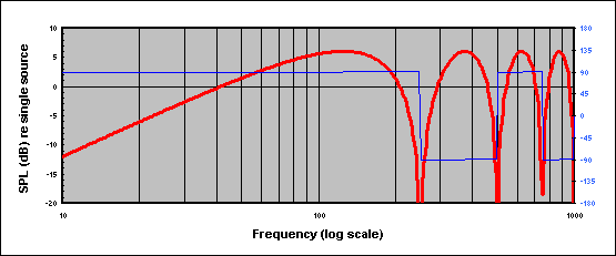
Fairly obviously, the LF output of the system is rolling off (at 6dB per octave), and there's a 90 degree phase shift everywhere. For simplicity, we'll assume that we're using the system only well below its transition frequency (at 125Hz), so it'll be possible to approximate a correction to this behaviour using a simple 6dB/octave low pass filter.
Rather than try to present sums, I'll attack this graphically. As a stimulus, I'll choose two cycles of 50Hz, preceded and followed by silence, like this:
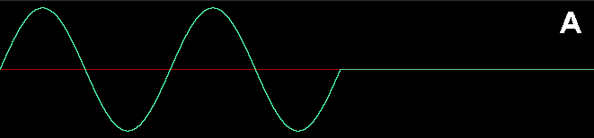
As Phil has shown, this signal contains frequencies above 50Hz and, in fact, it contains frequencies above the range that our sub can handle. We'll employ an 80Hz 24dB/octave low-pass crossover filter. This changes the waveform into this:
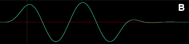
For comparison with what follows, the dashed line is positioned 10ms into the waveform.
So the above is what gets fed to our sub and is the target (ideal) response at the listening position. (Just in passing, note that the waveform has been lengthened by the filtering.)
If we use the system "uncorrected", the signal that reaches an on-axis far-field listener from the front source is the same as the above (ignoring time of flight) and the signal that reaches the listener from the rear source is the same thing but inverted in polarity and delayed by 4ms (2ms from the electrical delay added to the rear box and 2ms from the time of flight between the rear and front boxes). The rear arrival looks like this:
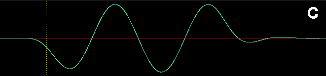
These two arrivals (at equal level, because we're in the far-field) add like this:
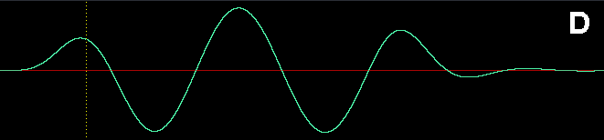
That's fairly obviously not what we want. It's also longer than the stimulus (which, I think, was Peter's point).
Now, here is how I think the system should ideally be used. First, the stimulus (B above) is passed through a 6dB per octave low pass filter. The result looks like this:
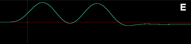
This is the signal that gets fed to the front source and reaches the listener unchanged. As before, the signal that reaches the listener from the rear source is inverted in polarity and delayed by 4ms, and looks like this:
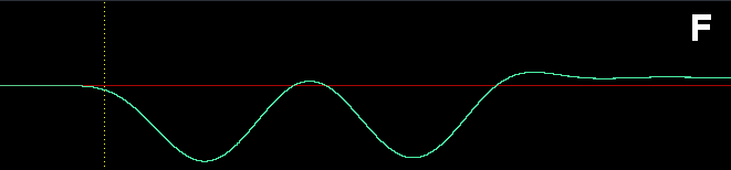
These two arrivals add like this:
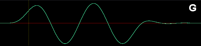
This is now back to being much more like it should. It's delayed relative to the original by about 2ms. (In all cases, btw, I've taken liberties with the vertical scaling for clarity.)
FWIW, the theoretical "corrected" response of the system looks like this:
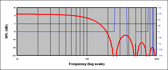
As well as the signal-processing aspect of this, there may also be a psychoacoustic concern regarding the "late arrival" from the rear source of the cardioid sub. We encounter late arrivals (echoes) all the time; everything we hear is accompanied by echoes off the surfaces around us. For a large range of delay times, the ear/brain is good at ignoring echoes, or perceiving minimal timbral change. If the delay gets long (20+ms), we start to hear separate arrivals. Very short echoes (such as those at issue here) cause timbral colouration because of the comb-filtering that they cause in the frequency domain. (See Peter Mapp's article. This is, however, in the context of full-spectrum material whereas we're dealing only with low frequencies.)
If the pressure-gradient system didn't work, we would also have problems with cardioid microphones and we'd be complaining about the late arrival of the out-of-polarity sound as it reached the rear of the diaphragm. (Of course, the distances involved in a microphone are tiny, but the frequencies involved are proportionally higher, and the situations are genuinely analogous.)
Further, one could say that every digital filter is achieving its effect using "late arrivals". The source signal is delayed by various amounts and each delayed copy is multiplied by some weight and added together. We don't worry about all these "late arrivals"; we just perceive the effect of the filter.
It would be interesting to know what corrections are built into commercial cardioid sub products.
Phil: how does your analysis stack up if you add in a 6dB/oct LPF (with -90 degrees of phase everywhere) before you start?
Nick
Post by: Mac Kerr on May 09, 2009, 12:18:01 PM
In the MAPP plots I posted earlier it is clear how much of an impact wall reflections have on the level throughout the room. Those plots show only the vertical walls, not the floor or ceiling, which would further complicate the reflections. What needs to be understood though is that MAPP is only displaying the level, based on arrival times. Inherent in that is the fact that there are multiple arrivals at every point in the room, and they too are causing time smear.
We are fairly used to the concept of keeping sound off big reflecting surfaces by aiming speakers, but at low frequencies this is not simple. By using these beam steering techniques we may be able to reduce the very complex interactions of wall reflections by replacing them with a more controlled interaction designed into the speaker array.
Mac
Post by: Phillip_Graham on May 09, 2009, 12:26:53 PM
| Nick Hickman wrote on Sat, 09 May 2009 11:29 |
If the pressure-gradient system didn't work, we would also have problems with cardioid microphones and we'd be complaining about the late arrival of the out-of-polarity sound as it reached the rear of the diaphragm. (Of course, the distances involved in a microphone are tiny, but the frequencies involved are proportionally higher, and the situations are genuinely analogous.) |
Well of course the cardioid microphone case is analogous, and it is the violation of the far-field that results in the observation of proximity effect, which is partly coming from the amplitude tailoring you are speaking of.
| Quote: |
Further, one could say that every digital filter is achieving its effect using "late arrivals". The source signal is delayed by various amounts and each delayed copy is multiplied by some weight and added together. We don't worry about all these "late arrivals"; we just perceive the effect of the filter. |
I alluded to this above in my post to Sebastian in mentioning the convolution theorem. I have a copy of Hamming's book at home
| Quote: |
Phil: how does your analysis stack up if you add in a 6dB/oct LPF (with -90 degrees of phase everywhere) before you start? Nick |
I don't know how I can type the thought experiment of a fixed phase shift in a way that would be remotely lucid here. Not only does that result in varying group delay, but it has to be considered at all frequencies in the passband to see the effects lucidly.
Your visual waveform view is far superior to any text rambling I could try to muddle through, and in the end the conclusion would match the one you have already exposited.
Perhaps this is the unspoken part so far. No one I know employing DIY cardioid subwoofers applies the additional low-corner LPF. They do invert/delay exclusively. I have seen it taught that way in almost every venue (eg SMAART class, SAC List). Indeed I have never personally implemented it the "correct" way in a live audio setting. I wasn't taught the "right" way, and only when thinking about microphones did it occur to me that I might be missing something.
If most (all?) practitioners are being taught the other way, and its implemented that way in the field, then the result is going to match the thought experiment above. And in that context the endfire is both theoretically and audibly better.
Now, its possible that the more astute manufacturers (e.g. Meyer D&B, Nexo, ADR) are doing this correctly. I am especially inclined to think that those doing it in the analog domain (i.e. Meyer and ADR) are doing it "right".
I have not had the opportunity to listen to a "known correct" cardioid case directly against an endfire of the same boxes. It would appear that is the next comparison that needs to take place.
Post by: Sebastiaan Meijer on May 09, 2009, 02:16:18 PM
Maybe I read to much, thanks for clarifying. Your preciseness in definitions is greatly appreciated, and much more elaborate than I can word it. Understanding the concepts versus being able to explain it clearly are definately 2 separate things (especially when you don;t know the English scientific terms from the top of your hat
Nick also made fantastic graphs. Regarding the microphone analogy: Yes I personally do favour omni's when possible. Especially in headsets omni's are often way more clear, not only due to the proximity effect, but also the 'chaos' that crosstalk between headsets give. And in the recording world the phase-correct response of omni's is well-known.
Let me try to summarize this discussion:
Cardiod:
- Pro: The least sound on the rear axis, and so for (nearly) every frequency.
Cons:
- Only coherently summing on a small passband. Creating ripples in frequency response above a certain frequency.
- Requires a LPF to correct LF roll-off. (and of course some gain after that to make up again) This makes the individual speakers reach their limitations earlier, making Dave Rat bring more subs to the show.
- Skewed impulse response / stretched envelope function as discussed at length above
- When the rear speaker does not get the same signal and filtering, or is built in a chamber with different tuning as the front facing speaker(s) the changes in phase response will make the whole thing even more complicated.
End-fired:
Pros:
- Coherent summing to the front over all frequencies
- No change in impulse response (on-axis)
Cons:
- FRequncy dependent cancelations to the rear
- Requires more depth in terms of placing.
Question:
- What are the physical limitations when the front cabinets are going to interfere with the reponse of the rear speakers due to physical size?
Please add when I missed something.
Sebas
Post by: Phillip_Graham on May 09, 2009, 07:59:10 PM
| Sebastiaan Meijer wrote on Sat, 09 May 2009 14:16 |
Hi Philip, and other posters, Maybe I read to much, thanks for clarifying. |
No harm, no foul, I hope!
| Quote: |
The amount of time required for the filter to envelope is however too much in the sub region for live audio. Newer implementations promise to improve here, but here my math-knowledge stops and I leave it to the DSP programmers. |
I am no DSP programmer, but consider this very consideration of the lower limit. You cannot manipulate the phase of a wave until you have defined the wave, and you cannot do that till you have one period of the wave. Thus this sets the absolute minimum delay time the "perfect" phase manipulating filter would incur.
Cardiod:
- Pro: The least sound on the rear axis, and so for (nearly) every frequency.
- Properly implemented provides broadband attenuation behind, like in a cardioid microphone!
I added one missing pro to your cardioid case, though it really applies much more for microphones.
Post by: Dave Rat on May 09, 2009, 08:04:15 PM
| Sebastiaan Meijer wrote on Sat, 09 May 2009 19:16 |
Hi Philip, and other posters, Maybe I read to much, thanks for clarifying. Your preciseness in definitions is greatly appreciated, and much more elaborate than I can word it. Understanding the concepts versus being able to explain it clearly are definately 2 separate things (especially when you don;t know the English scientific terms from the top of your hat Nick also made fantastic graphs. Regarding the microphone analogy: Yes I personally do favour omni's when possible. Especially in headsets omni's are often way more clear, not only due to the proximity effect, but also the 'chaos' that crosstalk between headsets give. And in the recording world the phase-correct response of omni's is well-known. Let me try to summarize this discussion: Cardiod:
Cons:
End-fired: Pros:
Cons:
Question:
Please add when I missed something. Sebas |
The summary is cool. Though the terms 'cardioid' and 'endfire' are loose and overlapping, they do serve to differentiate what is being discussed. I am not an expert in the cardioid nuances but would like to add the following.
Cardioid:
Under cons,the makeup gain that is required can have a serious effect on overall efficiency increasing the boxes and amps required to reach the same volume in front.
since the signal sent to front and rear speakers is different in EQ, level or both, the cardioid sub is susceptible to time/volume dependant non linearities in the dispersion.
End fire:
Under cons, the distance required to achieve pattern control is surprisingly short. I.E. effective pattern control can be realized by merely pointing a cabinet in reverse, next to or below cabs pointed forward. If delay is added to the forward facing cabs to 'wait' for the sound to wrap around front from the rear facing cab(s), a directional sub cluster can be created. Therefore, the additional space required to create a useful, functional and easy to setup endfire array takes exactly the same floor space as a conventional array.
Post by: Nick Hickman on May 09, 2009, 08:30:47 PM
Based mainly on playing with models, I see it like this:
Pressure-gradient advantages:
- Consistent pattern at all frequencies below upper limit
- Consistent frequency and phase response everywhere
- Consistent deep rear null extends to arbitrarily low frequency
- Needs less space between sources than end-fire (can be very compact)
Pressure-gradient disadvantages:
- Corrective EQ is costly to implement in terms of maximum output
- Potentially more sensitive to acoustic environment than end-fire
- Exhibits proximity effect (though probably not enough to worry about)
- Can't readily add more sources
End-fire advantages:
- Flat frequency response on-axis
- Combines coherently on-axis at all frequencies
- Easy to add extra sources (good for low frequency control but pattern narrows at higher frequencies)
End-fire disadvantages:
- Erratic pattern off-axis (varies with frequency)
- Pattern control collapses to omni at low frequency
- Useful pattern control only possible over an octave or so
- Erratic frequency and phase response far off-axis
- Needs more space between sources than pressure-gradient
The fact that the pressure-gradient response is consistent everywhere, incidentally, means that the previous examples hold good off-axis as well as on-axis (even though the amount by which the rear source arrival is being delayed changes) providing the high frequency limit of the stimulus is comfortably below the on-axis transition frequency (at least in a simple model).
That's a bit counter-intuitive. Put another way, it means, I think, that waveform X plus a copy of X inverted in polarity and delayed in time by T seconds is largely consistent in shape (and varies primarily in amplitude) for any value of T provided that X is constrained to frequencies well below 1/(2*T) Hz. The up-shot is that the far-field response of a pressure-gradient sub system can be consistent everywhere for frequency content well below 344/(4*D) Hz, where D is the physical spacing (in m).
Nick
Post by: Dave Rat on May 09, 2009, 08:36:04 PM
http://www.l-acoustics.com/manuels/SB28_UM_ML_1.0.pdf
http://www.audio-pro.nl/wx/download/download.php?id=11815967 82
To the best of my knowledge, they are both implemtations of what has gained the 'endfire' name in this thread. To the best of my knowledge, both use reversing boxes, delay and EQ to achieve a cardioid pattern over a limited bandwidth.
Keep in mind that subs typically only operate over a limited bandwidth, and the primary asset of the 'reversed polarity rear firing sub setup' is wide bandwidth cancellation behind.
I will say from personal experience, that these setups are power, simple, effective and clean sounding.
And perhaps some more thought should go into the title "Cardioid vs Endfire-Not the same thing" as though they are not the same, I continue offer that 'endfire' does offer a a cardioid pattern over a certain range of frequencies.
Or at least a cardioid-ish pattern that is as cardioid as the cardioid-ish pattern that the other setup can possibly offer if it's own myraid of issues are overcome.
http://mathworld.wolfram.com/Cardioid.html
Post by: Phillip_Graham on May 09, 2009, 09:05:14 PM
| Dave Rat wrote on Sat, 09 May 2009 20:36 |
These may be of interest: http://www.l-acoustics.com/manuels/SB28_UM_ML_1.0.pdf http://www.audio-pro.nl/wx/download/download.php?id=11815967 82 |
Its not clear what l-acoustics is doing from the manual, but clearly you are better positioned to know about the French loudspeaker guys than I!
It seems that D&B's implementation, based on reading between the lines in the manual, is indeed endfire by the "phil definition"
| Quote: |
And perhaps some more thought should go into the title "Cardioid vs Endfire-Not the same thing" as though they are not the same, I continue offer that 'endfire' does offer a a cardioid pattern over a certain range of frequencies. |
As I said to another person offline, one case is pressure gradient, the other is endfire, but both radiation patterns are cardioid(ish).
The reason I, personally, stick to my cardioid vs. endfire distinction is that the reversed polarity case owes its lineage directly to pressure gradient microphones, which have been popularly known as "cardioid microphones" for who know's how long.
| Quote: |
http://mathworld.wolfram.com/Cardioid.html |
{Topic Swerve}Mathworld is an amazing website, the breadth and depth of content is unbelievable!{/Topic Swerve}
Post by: Ivan Beaver on May 09, 2009, 09:42:56 PM
| Dave Rat wrote on Sat, 09 May 2009 20:04 |
[ The summary is cool. Though the terms 'cardioid' and 'endfire' are loose and overlapping, they do serve to differentiate what is being discussed. I am not an expert in the cardioid nuances but would like to add the following. Cardioid: Under cons,the makeup gain that is required can have a serious effect on overall efficiency increasing the boxes and amps required to reach the same volume in front. since the signal sent to front and rear speakers is different in EQ, level or both, the cardioid sub is susceptible to time/volume dependant non linearities in the dispersion. End fire: Under cons, the distance required to achieve pattern control is surprisingly short. I.E. effective pattern control can be realized by merely pointing a cabinet in reverse, next to or below cabs pointed forward. If delay is added to the forward facing cabs to 'wait' for the sound to wrap around front from the rear facing cab(s), a directional sub cluster can be created. Therefore, the additional space required to create a useful, functional and easy to setup endfire array takes exactly the same floor space as a conventional array. |
The terms may be overlapping, but the basic concepts are very different. The sub cabinet may both be in the same physical position for both cases-or not.
ENDFIRE: Both cabinets are facing the same direction and the front cabinet is delayed to the physical position of the rear cabinet-which is generally 1/4 wavelength of either the highest freq of the ingtended passband OR the center of the intended passband. This is really up to the end user and the patterns will vary with freq-so you have to determine what freq are more important to cancel.
There is no natural HF rolloff with enfire vs front radiating.
I have never seen an endfire situation in which the rear cabinet is facing the rear. Yes it can be done-but there is some directionality in the upper part of the passband, so the effective summation out front will not be the same as if both (or more) cabinets are facing forward. And the cancellations to the rear will not be the same-because of the actual freq response of the two cabinets involved are not the same. If they are both facing the same direction-the effective freq response of both cabinets in the rear direction is the same-making for a more effective cancellation (due to the physical and electronic delay)
The endfire works better if both cabinets are facing the same direction.
Endfire can be made up with as many cabinets as you want. It is not uncommon to have 4 cabinets lined up in a row. You cannot do this with a typical "Cardioid" configuration.
CARDOID: The rear cabinet is either forward or rear facing (with the driver physically behind the front driver by 1/4 wave length-at whatever freq you want) and is out of polarity with the front cabinet and delayed to the physical distance of the spacing. Rear facing is the "classic" cardioid configuration-but it can be forward facing as well-but the patterns will vary in coverage/cancellation/addition.
A Cardioid configuration has a natural HF rolloff of the passband-due to the arrival and spacing issues-as compared to a front radiating array.
If you apply different eq to the different cabinets-you will be shifting the phase of that particular cabinet (at that freq)and the end result will probably not be what you might think it is (in all areas).
The end result is not always what you might think it is. When I was doing my polar measurements of various endfire/cardioid arrays, I tried applying some eq to what I "thought" would make sense. Well it did make things a bit better out front-but really screwed up the rear rejection in very unfavorable ways.
You CANNOT simply make some adjustments "willy nilly" and listen at one position- you HAVE to listen to the overall coverage of the array and have a "before" and "after" measurement in order to be sure it is the overall "correct thing" to do.
That is one of the classic mistakes that people often make when doing sound system alignments (at any freq range)-they "fix" one area, while making another area much worse-because they are not "monitoring" what is happening in the other areas.
The issue that plagues all sound systems in all freq ranges is the interactions between freq and time-be it time of flight or electronic delay.
It is not as simple as is often thought.
Post by: Dave Rat on May 09, 2009, 10:31:01 PM
| Ivan Beaver wrote on Sun, 10 May 2009 02:42 |
I have never seen an endfire situation in which the rear cabinet is facing the rear. Yes it can be done-but there is some directionality in the upper part of the passband, so the effective summation out front will not be the same as if both (or more) cabinets are facing forward. |
Ahhh, hence the reason I am sharing this info. There has been lots of theory and various other descriptions here. It is very important to keep an open mind as well as keep things in perspective.
In my last post I provided links to two premium system manufacturers, L'Acoustics and D & B Audioteknik, that both offer cardioid sub array setups with processing that utilize exactly that, rear facing cabinets to form very effective 'endfire' cardioid sub setups that offer a big shovel full of pro's and a small spoonful of con's. In my opinion, of course.
Post by: Nick Hickman on May 10, 2009, 03:32:34 AM
| Dave Rat wrote on Sun, 10 May 2009 01:36 |
And perhaps some more thought should go into the title "Cardioid vs Endfire-Not the same thing" as though they are not the same, I continue offer that 'endfire' does offer a a cardioid pattern over a certain range of frequencies. |
The terms "pressure-gradient" and "end-fire" may be better. Just in case anyone still isn't clear, the fundamental difference is that pressure-gradient systems achieve their rear null using a polarity inversion (which works at all frequencies) whereas end-fire systems achieve their rear null using a time of flight that equates to 180 degrees (which gives a different pattern of nulls at every frequency).
Nick
Post by: Peter Morris on May 10, 2009, 08:47:48 AM
This is an interesting compromise.
As you know, the compromise I was describing requires setting the *total delay of the rear box to 1/2 the wave length of the pass band’s middle frequency. That way every thing lines up around (say) 62 Hz. This results in a minimal a phase difference between the two signals (one is inverted) over the pass band. It will be close enough at 40Hz and 80 Hz so that every thing sums almost flat, producing maximum SPL.
What you have done is to set the delay close to the high end of the pass band - 125Hz; this results in a lost about 6dB from acoustic phase cancellation by the time you are down to 40Hz.(your first graph)
To correct this, you have added a 6dB LP filter to both inputs which more or less fixes everything up except you have lost some output capability as above - which may or may not be important.
FWIW Your plot B is the waveform I was trying to describe. When you sum the two you get - plot D, note how the first part of the wave form is reduced in amplitude. That’s the lack of punch I described. I actually posted a hand drawn version of this on the LAB about 5 years ago; although I don’t think anyone got it at the time.
Regards
Peter
*total delay = path length delay - 4 ft + electronic delay - 4ms
Post by: Joseph_Pearce on May 10, 2009, 11:57:45 AM
For what it's worth I didn't like the sound of card sub arrays BECAUSE of that polarity inversion. Peter Morris mentions this as well.
Does this filter fix this? Is this why some "in-box" cardioid subs sound sluggish? I have deployed end-fire type arrays before and I feel that I have a full grasp for how these work, it is just this last little piece of the "cardioid" puzzle that I am having trouble with. Thanks.
And thanks for the waveforms!
Post by: Ivan Beaver on May 10, 2009, 01:12:36 PM
There were also some small errors in laying out the points on the measurement circle-so there are some "irregularities" in the actual polars. Ie not being equal on corrisponding angles.
However there was a lot of good information gathered (most of it is just in my head-as I saw the final polars when displayed-and getting fuzzier day by day).
I did do some screen captures of some of the polars and the only ones I have that are worth showing are the following ones.
When I get some time, I will repeat the process (with more precision), but that will likely not take place for several months as I am REALLY busy right now.
Below are two graphs of the same physical placement of loudspeakers-only the polarity and delay times were changed. The level remained equal to all loudspeakers
I measured them the way I did (in this case) so whether they were facing forward or rear did not affect the results.
The layout is as follows. 4 Danley TH minis laid end to end, with 2 sets of mouths touching. This results in a 75Hz spacing (45") from the center of one pair of mouths to the center of the other pair of mouths.
The cabinets used in this layout only go to 50hz, so that is partially why the lower data points are so odd looking.
The cabinets are all facing straight up in the air (that is why the direction does not affect the result). I don't ever see a case that you would actually do it this way-but could see the exact opposite-in fact i have done it that way. Facing downward when flown in a room.
The measurement circle was 135' diameter.
The top graph is a typical cardioid alignment with the rear cabinet(s) out of polarity and delayed. The bottom graph is endifre with the front cabinets delayed to the rear position.
As you can see, while there are some similarities, there are a lot of differences as well.
Anyway-take it for what it is and maybe will spark more interest in actually MEASURING some responses.
Post by: Phillip_Graham on May 10, 2009, 01:26:38 PM
| Joseph Pearce wrote on Sun, 10 May 2009 11:57 |
I guess that this is specifically posted for Nick to answer as it seems to me that he has brought something new to the Cardioid sub setup, a 6db low pass filter...could you please explain this a little more? I do not understand. |
This part is not "new" per se.; the tailored response is discussed in documents on pressure gradient microphones. I think this is discussed in detail in Neumann's microphone treatise. Let me see if I can dig up the specific locations.
It is "new," in this specific setting, because it is not normally applied when people discuss how to make a cardioid array in places like here.
| Quote: |
Does this filter fix this? Is this why some "in-box" cardioid subs sound sluggish? I have deployed end-fire type arrays before and I feel that I have a full grasp for how these work, it is just this last little piece of the "cardioid" puzzle that I am having trouble with. Thanks. |
The filter does not "fix" all of the effects, but it does improve them greatly. The applied LPF changes both the relative amplitude and group delay, of each frequency component in the waveform envelope, and this realigns the resultant summation of all the components much closer to the original.
I am sure Nick will flesh this out further, including perhaps discussion of a modified filter transfer function that restores the original exactly.
Post by: Phillip_Graham on May 10, 2009, 02:39:52 PM
Since Evan K is (indirectly) responsible for one of the most interesting threads in memory here, and for me to think a lot harder about audio than I have in quite a while, I think it is only appropriate to reward him by metaphorically throwing him under the coach he is currently riding in!
The beauty (horror?) of mixing a band beloved by teens of the Youtube generation is that they record everything for posterity, and post it online!
With the search string "All Time Low live" coupled with 5 minutes of finding (relatively) unmolested audio, I present to you Evan K, king of the Clair center clustered subwoofers, at work:
http://www.youtube.com/watch?v=Wa0At0PRMbo
http://www.youtube.com/watch?v=kt6jTciFZfk
http://www.youtube.com/watch?v=Qy1LoH5q4P0
http://www.youtube.com/watch?v=g2DewGEeMik
http://www.youtube.com/watch?v=6qzCKUB6ia4
Cheers to you Evan, a young man who couldn't hide his mixing from the LAB even if he tried!
All in good fun, my friend!
Post by: Nick Aghababian on May 10, 2009, 02:54:42 PM
| Phillip Graham wrote on Sun, 10 May 2009 14:39 |
Well, Since Evan K is (indirectly) responsible for one of the most interesting threads in memory here, and for me to think a lot harder about audio than I have in quite a while, I think it is only appropriate to reward him by metaphorically throwing him under the coach he is currently riding in! The beauty (horror?) of mixing a band beloved by teens of the Youtube generation is that they record everything for posterity, and post it online! With the search string "All Time Low live" coupled with 5 minutes of finding (relatively) unmolested audio, I present to you Evan K, king of the Clair center clustered subwoofers, at work: http://www.youtube.com/watch?v=Wa0At0PRMbo http://www.youtube.com/watch?v=kt6jTciFZfk http://www.youtube.com/watch?v=Qy1LoH5q4P0 http://www.youtube.com/watch?v=g2DewGEeMik http://www.youtube.com/watch?v=6qzCKUB6ia4 Cheers to you Evan, a young man who couldn't hide his mixing from the LAB even if he tried! All in good fun, my friend! |
After watching those videos I can see why Evan always complains about not enough sub! I can barely hear it from the camera!
Post by: Phillip_Graham on May 10, 2009, 03:06:27 PM
| Nick Aghababian wrote on Sun, 10 May 2009 14:54 |
After watching those videos I can see why Evan always complains about not enough sub! I can barely hear it from the camera! |
Perhaps you are jesting, but in reality there is plenty of subbage if Evan is at the board!
Many many of the cheapie camera mics totally crap out on bass/toms/kick in videos of ATL. The ones that don't also don't have any low end. Since I thought no one wants to hear "fart" "fart" "fart" for 3 minutes on youtube, you get videos without much low end
Post by: Milt Hathaway on May 10, 2009, 03:09:40 PM
| Phillip Graham wrote on Sun, 10 May 2009 13:39 |
The beauty (horror?) of mixing a band beloved by teens of the Youtube generation is that they record everything for posterity, and post it online! With the search string "All Time Low live" coupled with 5 minutes of finding (relatively) unmolested audio, I present to you Evan K, king of the Clair center clustered subwoofers, at work: |
Well, that ruins the "On the internet, no one can hear you mix" sig.
Post by: Nick Aghababian on May 10, 2009, 03:12:34 PM
| Phillip Graham wrote on Sun, 10 May 2009 15:06 | ||
Perhaps you are jesting, but in reality there is plenty of subbage if Evan is at the board! Many many of the cheapie camera mics totally crap out on bass/toms/kick in videos of ATL. The ones that don't also don't have any low end. Since I thought no one wants to hear "fart" "fart" "fart" for 3 minutes on youtube, you get videos without much low end |
Post by: Andy Peters on May 10, 2009, 07:26:55 PM
| Milt Hathaway wrote on Sun, 10 May 2009 12:09 | ||
Well, that ruins the "On the internet, no one can hear you mix" sig. |
Well, fuck me up a rope.
Seriously -- this thread makes up for a lot of the "what mic kit" threads here of late. Editing it and making it a sticky is a good idea.
And on topic, I was at the 9:30 Club in DC in March, and the d+b rig has cardiod subs, 3 boxes of B2 per side, middle box facing back. After the set, the guys in the band said, "wow, there was a lot of low end on the stage" which really surprised me.
-a
Post by: Uwe Riemer on May 10, 2009, 07:38:19 PM
this thread made me think a lot, this is actually the way I use this forum
therefore this is not a reply but maybe a good place to chime in.
to Nick:
I am not sure, if the the pressure gradient model applies to the cardioid array with the backfiring woofer with inverted polarity.
I pressed Mapp online hard to find a pattern with perfect null to low frequencies and had no success, maybe I am to stupid or- that would be the other explanation- there is a lot more distance involved with two sub than with a microphone capsule.
to the impulse-response discussion part:
Virtual SIM offers an impulse prediction, the only assumption would be, that the Meyer guys did their job well.
to the on-axis gain part:
I am not interested in on-axis gain considerations, my job is to provide most possible even distribution of sound for a given location, the on-axis gain considerations apply for Tops as for Subs,
BTW every kind of directivity changes the impulse response.
to Ivan and his real world measuring:
thanks
Uwe
Post by: Peter Morris on May 11, 2009, 03:42:00 AM
It’s particularly interesting when you look at them over the desired band width, especially when you consider what we want out of this – Great sound for the audience - and BTW they don’t care about the accuracy of the cardioid pattern.
What matters is that the subs sound great consistently through out audience, that reverberant issues associated with the subs are minimised, and the acoustic environment is pleasing for the musicians. In addition, minimizing the number of boxes required may also be an issue.
I suspect that in practice difference between “cardioid” and “end-fire” in this respect is some what irrelevant, possibly favouring “end fire”.
An interesting point to consider is to look at what happens in a hypothetical case as the frequency limit approaches zero – DC. The output of the “cardioid” goes to zero, the “end-fire” remains constant but looses all pattern control.
Peter
Post by: Nick Hickman on May 11, 2009, 08:24:14 AM
| Peter Morris wrote on Sun, 10 May 2009 13:47 |
length of the pass band’s middle frequency. That way every thing lines up around (say) 62 Hz. This results in a minimal a phase difference between the two signals (one is inverted) over the pass band. It will be close enough at 40Hz and 80 Hz so that every thing sums almost flat, producing maximum SPL. |
I'm afraid I don't follow the context. Could you detail the spacings and delays you're advocating? If, in a pressure-gradient case, the delay selected doesn't "match" the spacing of the sources, the result is a cardioid "family member" pattern (i.e. hypercardioid, etc.) rather than actual cardioid. But whatever the pattern is, it's consistent from above the transition frequency on down as low as you want to go.
Joseph:
| Joseph Pearce wrote on Sun, 10 May 2009 16:57 |
I guess that this is specifically posted for Nick to answer as it seems to me that he has brought something new to the Cardioid sub setup, a 6db low pass filter...could you please explain this a little more? I do not understand. |
It's simply an observation that the frequency-domain effect of the two arrivals of a theoretical (modelled) pressure-gradient (cardioid) arrangement is to create a low frequency response (below transition frequency, i.e. the frequency where the two sources sum coherently before the response dives into comb filtering) that rolls off at 6dB per octave (the sloping line in this picture) and that this could be corrected using an "inverse" low pass filter leaving only some delay (like this). But there's a price to pay in terms of output.
Phil:
| Phillip Graham wrote on Sun, 10 May 2009 18:26 |
The filter does not "fix" all of the effects, but it does improve them greatly. The applied LPF changes both the relative amplitude and group delay, of each frequency component in the waveform envelope, and this realigns the resultant summation of all the components much closer to the original. I am sure Nick will flesh this out further, including perhaps discussion of a modified filter transfer function that restores the original exactly. |
You mean something like creating a FIR filter with the inverse of the predicted response, including that around the transition frequency? That would, I think, work on-axis (or for whatever position it was calculated), but wouldn't work generally because the effective transition frequency gets higher as the listener moves further off-axis (and the rear arrival gets earlier). I think the best you can do is the LPF and the results should be pretty good if the system is only used below TF.
I do find it quite mentally challenging to rationalise that I know I still have two arrivals and that the spacing between them varies as I move around, yet, for all far-field listening positions, I end up with an ideal impulse response (up to some freq limit). Of course, this all assumes that the two sources are identical and, to whatever extent they're not (directional, different acoustic environments, non-linear), there'll be problems.
Or were you thinking of something else?
Ivan:
| Ivan Beaver wrote on Sun, 10 May 2009 18:12 |
The top graph is a typical cardioid alignment with the rear cabinet(s) out of polarity and delayed. The bottom graph is endifre with the front cabinets delayed to the rear position. |
Despite any shortcomings, that's very helpful. Thanks. If you do repeat the test, it might help to subtract out the raw loudspeaker response so that one can more readily see the level differences caused by the directional system.
Uwe:
| Uwe Riemer wrote on Mon, 11 May 2009 00:38 |
I am not sure, if the the pressure gradient model applies to the cardioid array with the backfiring woofer with inverted polarity. |
I believe it does. A Google search finds this by Harry Olsen which might be relevant (but I don't have the text).
Nick
Post by: Eytan Gidron on May 11, 2009, 08:46:47 AM
| Matthew Knischewsky wrote on Fri, 24 April 2009 22:26 |
If you have enough DSP, this is what to try next. starting with the center 2 subs at 0ms, apply .5 ms delay to each sub on either side of the center pair. Now add .5 more delay to the next outside pair, (1ms) and so on. until you get to the outsides of the array. you might not even need .5ms per pair to cover the venue, but it's a start. If you don't have enough DSP channels you can physically place the subs in an arc to create delay. Matt |
Maybe someone already mentioned this Powersoft arc calculator, I haven't read all the 170+ posts.
We did a large outdoor (50,000) Depeche Mode show last night and we tried out this "center subwoofer arc delay" configuration. I used this calculator taken from the Powersoft website :
http://pro-audio.powersoft.it/download_list.php?use_in=45&am p;id_menu=357&sub_cat=63
It worked very well. I made a few presets on the XTA processor. Each preset had a different horizontal coverage. The wider the pattern, we had less level and punch at FOH. It worked very well but we didn't end up using it as we were told that that Dave, the lead singer doesn't like to have the subs in front of the stage. This is a "bass heavy" show.
We ended up using the traditional two stacks (L/R) configuration. The subs were 16 aside Turbo 21s. The main hang was 16 Vertecs + 10 flown Vertec subs aside. As Anthony, the BE wanted as much low end as he could get, we also added 8 x L-Acoustics SB118 aside. It took quiet some time to align them all, but in the end we had good punch and a decent coverage (although not as smooth as with the delayed arc subs).
Post by: Doug Fowler on May 11, 2009, 10:58:40 AM
| Quote: |
And on topic, I was at the 9:30 Club in DC in March, and the d+b rig has cardiod subs, 3 boxes of B2 per side, middle box facing back. After the set, the guys in the band said, "wow, there was a lot of low end on the stage" which really surprised me. |
In an enclosed space, all bets are off with the cardioid sub setups. Near the rear of the card setup there will be be plenty of bass, typically attenuating a short distance away. With CD-18s ten feet is a good rule of thumb.
Post by: Peter Morris on May 11, 2009, 11:32:44 AM
| Nick Hickman wrote on Mon, 11 May 2009 13:24 | ||
Peter:
I'm afraid I don't follow the context. Could you detail the spacings and delays you're advocating? If, in a pressure-gradient case, the delay selected doesn't "match" the spacing of the sources, the result is a cardioid "family member" pattern (i.e. hypercardioid, etc.) rather than actual cardioid. But whatever the pattern is, it's consistent from above the transition frequency on down as low as you want to go. |
Hi Nick,
I think I said “*total delay of the rear box to 1/2 the wave length of the pass band’s middle frequency.”
And defined total delay at the bottom as
*total delay = path length delay - 4 ft + electronic delay - 4ms
By that I meant 4 ft between the speakers with 4 ms of delay
4 ft and 4 ms were approximate values that were some where near the mark for the sake of explanation. (roughly 1ft = 1ms)
Peter
Post by: Ken Freeman on May 11, 2009, 11:57:12 AM
Ken
Post by: Mac Kerr on May 11, 2009, 12:10:44 PM
| Ken Freeman wrote on Mon, 11 May 2009 11:57 |
As Doug noted, the plans do tend to go out the window when you have to deal with a building where you may not have all the info until load in. Ken |
More importantly indoors, reflections can become the dominant determiner of coverage.
http://srforums.prosoundweb.com/index.php/m/429079/44778/0// /377/#msg_429079
http://srforums.prosoundweb.com/index.php/m/429042/44778/0// /377/#msg_429042
Not only is level effected by reflections, but don't forget that every one of those interactions represents a time error. Those loud and soft spots are caused by phase errors that are due to different arrival times. Outdoors we worry about time smear due to the changing phase relationship between elements of a steered bass array, indoors those differences are likely to be swamped out by the effects caused by reflections.
Mac
Post by: Ivan Beaver on May 11, 2009, 01:00:18 PM
| Nick Hickman wrote on Mon, 11 May 2009 08:24 | ||
Ivan:
Despite any shortcomings, that's very helpful. Thanks. If you do repeat the test, it might help to subtract out the raw loudspeaker response so that one can more readily see the level differences caused by the directional system. |
Here are some overlays from the individual cabinet responses. The are individual measurements at each position on the circle, so the levels are the same going to the cabinets.
The top graph is the 0
Post by: Nick Hickman on May 11, 2009, 01:05:52 PM
| Peter Morris wrote on Mon, 11 May 2009 16:32 |
I think I said “*total delay of the rear box to 1/2 the wave length of the pass band’s middle frequency.” And defined total delay at the bottom as *total delay = path length delay - 4 ft + electronic delay - 4ms By that I meant 4 ft between the speakers with 4 ms of delay 4 ft and 4 ms were approximate values that were some where near the mark for the sake of explanation. (roughly 1ft = 1ms) |
Fair enough. In a theoretical system, the slight amount of excess delay (4ft == 3.54ms, so you have about 0.5ms extra) leads to a "wide cardioid" pattern (and a slight lowering of the transition frequency). At 70Hz, for example, it gives the first polar below (5dB per division; heavy circle represents a single source) whereas an exact delay of 3.54ms gives the second polar. FWIW, if you err in the opposite direction (3ms), you'd get the third (hypercardioid) pattern.
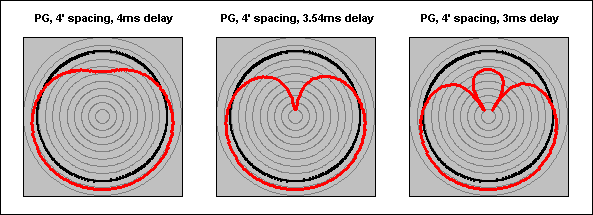
Nick
Post by: Jens Brewer on May 13, 2009, 02:51:49 AM
a) In your first diagram ( http://srforums.prosoundweb.com/index.php/m/0/44778/120/4379 /#msg_433247 ) the blue phase line swings between +/-90 relative to the rear box (which is polarity reversed relative the 'normal' front box). When you get to the theoretical 'corrected' response at the end of the post, we're back to a 'normal' 0 degrees over the relevant bandpass. But that is still relative to the rear polarity reversed box, right? So in effect, the front box is now reverse polarity relative to the original drive signal?
b) Is the theoretical 'corrected' response: (native cardioid response + 1st order 125hz LP + 4th order 80hz LP) or just (native cardioid response + 1st order 125hz LP)? Just eyeballing a 6db LP over the first graph looks like it would do it, but I want to be sure I'm not assuming something I shouldn't.
c) Was there a reason you used 125hz box spacing (.688m/2ms) but used a fourth order 80hz LP? Since we're dealing with a purely hypothetical sub here, and not tailoring the electrical crossover to a measured response, can I assume that you actually want the subs to crossover around 80hz? Wouldn't we be better off to set the spacing to match (1.07m/3.13ms)? It would push the rolloff slope further down, keeping more of the additive gain in the useable bandpass, and likewise, the first cancellation will occur lower, right about where the mains should start to shoulder the load.
d) I've done cardioid sub setups quite a bit and have not measured the drastic 'uncorrected' 6db rolloff that theory would predict. In most cases that I can remember, I didn't get results onaxis that were significantly different than the response of a single box (magnitude excepted). Could this be a function of being indoors for 99% of my gigs, some sort of extra processing that manufacturers have got going on, or perhaps operator error? If this kind of response were the norm, I would have expected it would have been picked up earlier by someone like Dr. Don, 606, Mauricio, etc. (Not to besmirch your effort here in any way.) In the original diagram you have not accounted for the natural bandpass of a sub box and attendant group delay. Could this be the missing piece?
e) Last question (and this is not directed just to Nick): best practices regarding phase alignment of subs to mains when using cardioid subs. I've been in the habit of having both subs on to set level, kill the rear sub to do the alignment with the mains, then restore and check. The 'time smear' should have an effect on phase since our spacing is only accurate for one frequency, right? How significant, if at all, is the change of the phase slope between one on / both on?
Great post....got my gears going.
Post by: Langston Holland on May 13, 2009, 11:24:46 AM
| Ivan posted the following measurements on Mon, 11 May 2009: |
Your measurements have a couple of fascinating things in common with the ones I made a few years ago with EAW's BH760 subs. Notice how the end-fire arrangement (green trace) has a greater rear rejection in the 70Hz area whereas the card arrangement (purple trace) has greater rear rejection above and below this "tuning point". The end-fire also has a smoother trace than the card at the rear. I should have expanded the frequency axis as you did to make things clearer. I've been fussed at about that in the past. :)
Post by: Nick Hickman on May 13, 2009, 01:29:51 PM
| Jens Brewer wrote on Wed, 13 May 2009 07:51 |
a) In your first diagram ( http://srforums.prosoundweb.com/index.php/m/0/44778/120/4379 /#msg_433247 ) the blue phase line swings between +/-90 relative to the rear box (which is polarity reversed relative the 'normal' front box). When you get to the theoretical 'corrected' response at the end of the post, we're back to a 'normal' 0 degrees over the relevant bandpass. But that is still relative to the rear polarity reversed box, right? So in effect, the front box is now reverse polarity relative to the original drive signal? |
The phase plot was "relative to the rear source" in the sense that the rear source was the origin for ignoring time of flight, not in the sense of being relative to the (inverted) signal being sent to the rear box. I chose this reference for simplicity in the example since it makes the combined on-axis phase flat.
| Quote: |
b) Is the theoretical 'corrected' response: (native cardioid response + 1st order 125hz LP + 4th order 80hz LP) or just (native cardioid response + 1st order 125hz LP)? Just eyeballing a 6db LP over the first graph looks like it would do it, but I want to be sure I'm not assuming something I shouldn't. |
Yes, the only change was to illustrate the effect of a low-pass filter.
| Quote: |
c) Was there a reason you used 125hz box spacing (.688m/2ms) but used a fourth order 80hz LP? Since we're dealing with a purely hypothetical sub here, and not tailoring the electrical crossover to a measured response, can I assume that you actually want the subs to crossover around 80hz? Wouldn't we be better off to set the spacing to match (1.07m/3.13ms)? It would push the rolloff slope further down, keeping more of the additive gain in the useable bandpass, and likewise, the first cancellation will occur lower, right about where the mains should start to shoulder the load. |
I think the 80Hz came from Peter's earlier example. I chose the delay to keep the example below the transition frequency. In practice, I think you make a very good point and you'd want to use more of the frequency region where the signals from the two sources are arriving in phase on axis (though that dilutes the effectiveness of the example!).
| Quote: |
d) I've done cardioid sub setups quite a bit and have not measured the drastic 'uncorrected' 6db rolloff that theory would predict. In most cases that I can remember, I didn't get results onaxis that were significantly different than the response of a single box (magnitude excepted). Could this be a function of being indoors for 99% of my gigs, some sort of extra processing that manufacturers have got going on, or perhaps operator error? |
Were your observations based on "DIY" pressure-gradient systems where you did the delay and polarity inversion (and nothing else) or on a manufacturer's "packaged" system? Real subs doubtless deviate significantly from being omnidirectional point sources (the world that the response graphs occupy), but I'm not sure what mechanism would cause a real system to exhibit more LF output than a simple model would suggest (though I've certainly heard it suggested before). Perhaps Phil can help?
| Quote: |
e) Last question (and this is not directed just to Nick): best practices regarding phase alignment of subs to mains when using cardioid subs. I've been in the habit of having both subs on to set level, kill the rear sub to do the alignment with the mains, then restore and check. The 'time smear' should have an effect on phase since our spacing is only accurate for one frequency, right? How significant, if at all, is the change of the phase slope between one on / both on? |
If you align with only the front source, the combined phase will certainly be different when you add the rear source. The phase of both sources combined will be 0 degrees (relative to the front source only) at the effective transition frequency and slope down. The effective transition frequency, of course, changes as you move off-axis. What was your thinking behind aligning with only the front source?
Nick
Post by: Jens Brewer on May 15, 2009, 11:24:59 AM
| Nick Hickman wrote on Wed, 13 May 2009 13:29 | ||
Yes, the only change was to illustrate the effect of a low-pass filter. |
Sorry if my question was not clear Nick, but is it 2 LP filters or just one on the corrected response?
| Quote: |
Were your observations based on "DIY" pressure-gradient systems where you did the delay and polarity inversion (and nothing else) or on a manufacturer's "packaged" system? |
In this case, they were DIY with everything from Meyer to Mackie subs. Hence my question/observation. Perhaps I haven't noticed simply because I'm crossing over low enough, that the area where you're getting negative summation (ie. the lowest part of your graph) is where the boxes start to fall off anyway.
| Quote: |
If you align with only the front source, the combined phase will certainly be different when you add the rear source. The phase of both sources combined will be 0 degrees (relative to the front source only) |
If front box=0 and adding the rear box=0, are they not then congruent? They only differ in their arrival times, not phase, in relation to the original drive signal. Perhaps I'm too thick to see what you were pointing out?
| Quote: |
What was your thinking behind aligning with only the front source? |
Better coherence. Hard as I try, I'll never get a perfectly on-axis measurement point, and measuring two slightly different signals at nearly equal level at the same time has drawbacks. Working from memory here, I don't think I've ever noticed a dramatic change of phase slope when I added the rear box back in. Maybe I wasn't looking close enough?
Thanks again.
Post by: Nick Hickman on May 16, 2009, 09:48:28 AM
| Jens Brewer wrote on Fri, 15 May 2009 16:24 |
Sorry if my question was not clear Nick, but is it 2 LP filters or just one on the corrected response? |
Sorry for the unclear answer! I think you're talking about this response graph relative to this one. If so, the only change was the addition of a 6dB/octave low pass.
| Quote: |
If front box=0 and adding the rear box=0, are they not then congruent? They only differ in their arrival times, not phase, in relation to the original drive signal. |
I'm not quite sure what you mean by "front box=0" and "rear box=0"; sorry if I'm being dim.
Still occupying the world of omnidirectional point sources here ...
If the front source is the physical reference point, then the rear source arrives in phase at the transition frequency. (In a classic cardioid system, the on-axis TF is where the delay and the source spacing both correspond to a quarter wavelength, so the rear source has 90 degrees from the delay and 90 degrees from the time of flight, giving 180 degrees total, plus the polarity inversion.)
An octave lower, we only have 45 degrees from the delay and 45 degrees from the time of flight, giving 90 degrees total, plus the polarity inversion. An octave higher, we have 180 degrees from the delay and 180 degrees from the time of flight, leaving just the polarity inversion, and resulting in the first comb filter null. At very low frequency, we have close to nothing from delay or time of flight (i.e. very long wavelength).
Put everything together, and (for your previous example: 1.07m spacing, 3.11ms delay, TF=80Hz) the phase of the rear source (relative to the front source) on-axis looks like this:
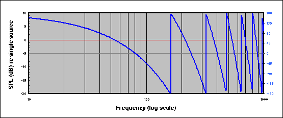
Add in the front source too, and the phase of the combined signal (far-field on-axis) looks like this:
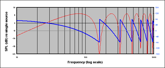
As you move off axis, the entire curve moves up in frequency as the effective TF gets higher (because the time of flight delay on the rear source is reduced relative to its value on-axis). At 45 degrees off-axis, for example, you see this:
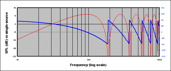
(BTW, it's a bit unintuitive, but adding a sine at 0 degrees to an equal amplitude sine at 90 degrees gives a sine with +3dB amplitude at 45 degrees.)
Does that make sense?
Nick
Post by: HarryBrillJr. on August 02, 2009, 05:51:58 PM
| Phillip Graham wrote on Fri, 24 April 2009 13:13 |
I should clarify that I like the cardiod solution more than the arced and/or progressive delay approaches because those can cause a large lobe of LF to show up right in the center of the stage. |
Although this is true for arced lines, it is not true for delay arced straight lines. In that case the arc effect works in both directions.
Post by: HarryBrillJr. on August 02, 2009, 05:58:57 PM
| Phillip Graham wrote on Fri, 24 April 2009 16:33 | ||
Art, The subwoofers are going to form a virtual dipole by coupling to the floor in the vertical plane. Whenever LF boxes are placed against a solid boundary, its important to remember the boundary causes "virtual boxes" in the floor, creating basically a 2-high subwoofer array. That is why in cardiod sub setups you reverse the box closest to the boundary, and not farthest away. This insures the canceling boxes are closest to the center of the "virtual array", and that the vertical lobe behavior of the array is also the cardiod pattern you seek. If the system was setup as shown, and then aligned in the vicinity of FOH, its not surprising that the relative bass amount other places in the arena was low. Its also possible, but less likely that the slap back from the rear wall of the arena was cancelling some of the forward sub energy at important mix frequencies in the audience. There is always the possibility of catching an unusual room mode in the acoustic space, but my guess is that this was more a function of the alignment sounding right at FOH, but causing insufficient bass in the rest of the venue due to the directivity of the bass array. Physics is physics, and this remains the most likley explanation. PS I don't know any of the system teching details for sure, I really don't want to seem like I am slagging on the CBA guy from my armchair. Just consider it helpful musings. |
I would agree and also add that it seems likely without appropriate measurements, given my experience there may indeed be a lot of overlap as Art suggested. Just because the crossover says 80Hz doesn't mean the boxes are really crossing over there.
Post by: HarryBrillJr. on August 03, 2009, 12:47:39 PM
| Mac Kerr wrote on Wed, 29 April 2009 14:59 | ||
In either case you have to use a time offset between the front and rear firing speakers. If all you do is put 1 effectively omni speaker out of polarity with the rest you get no pattern control, and you get cancellation to the front and rear equally as you say. My point was merely that the rear facing speaker is in fact creating pattern control via cancellation. Whether or not the rear facing box is in or out of polarity will have less effect than the time offset between the boxes. Below are 3 models, the first is with the bottom rear facing box out of polarity, and delayed by 4ms. The second is with all 3 boxes with the same polarity, but the forward facing boxes delayed 4ms. the third is with the bottom box out of polarity, but no delay. It is clear this is not useful. This is a half space model at 63Hz, the gain is the same to all speakers. The cancellation and forward gain characteristics will change with frequency, but can be similar in either scenario. |
Just a quick note on this. The first scenario with the rear speaker delayed and polarity inverted has pattern control over the WIDEST frequency range. The second scenario with the front delayed and all boxes with the same polarity has the best subjective sound quality out front.
When I originally read Dave's blog a couple years ago and then saw and heard his array for the Peppers, it was my understanding that he did NOT like the d&b "cardioid" setup that Nexo also uses but does not mind the sound of an "End Fire" array. I came to this conclusion even while the engineer for Gnarls made snarky comments about Dave not liking cardioid and yet he was using cardioid.....and apparently passed on using the split hangs. The mix quality of the 2 acts said all that needed to be said there. Sometimes the young techy types need to close there eyes and listen to the sound rather than spend lots of time programming plugins on a digital desk while incoherent vocals and a wash of mud come out of the PA. I'll be the first to tell you, LISTENING is by far the most important tool we have to get great sound. Smaart, etc are simply tools to help us get where we know we already know we want to go, faster.
I also agree that End fire is an implementation and cardioid is a polar pattern. In the cases above none of them are End Fire implementation. If anyone has an official name for this type of stack (one box facing the rear), I'd like to know it. Again, cardioid is a polar pattern. You can can see there are several possible polar patterns that can be obtained from a particular deployment.
I hope I was clear on this post. I have to step out and I kind of rushed it. Interesting thread so far. I had not read past the first post before. Just looked like another concert sound quality review.
Post by: HarryBrillJr. on August 04, 2009, 12:48:41 AM
Post by: Guy Johnson on August 04, 2009, 05:38:49 PM
Anything that reduces bass excitation in reverberant spaces has to be A Good Thing, and any technique that will give a tighter, better bass-end, I want to know about—especially if it can easily be applied by people like me, (I normally use a maximum of 4 bass bins). Though knowledge of the theory, and the practical pitfalls of bass steering in bigger events is great ... Some of this in the tech specs for festivals and bands will wake up those PA companies and designers with their heads in the sand: I've heard ghastly bass far too often, and been embarrassed FOH engineering in such woodgy, mushy & boomy messes. Even a choice of sending to different bass systems, would be useful.
Post by: HarryBrillJr. on August 04, 2009, 09:55:56 PM
| Sebastiaan Meijer wrote on Sat, 09 May 2009 13:16 |
Hi Philip, and other posters, Maybe I read to much, thanks for clarifying. Your preciseness in definitions is greatly appreciated, and much more elaborate than I can word it. Understanding the concepts versus being able to explain it clearly are definately 2 separate things (especially when you don;t know the English scientific terms from the top of your hat Nick also made fantastic graphs. Regarding the microphone analogy: Yes I personally do favour omni's when possible. Especially in headsets omni's are often way more clear, not only due to the proximity effect, but also the 'chaos' that crosstalk between headsets give. And in the recording world the phase-correct response of omni's is well-known. Let me try to summarize this discussion: Cardiod:
Cons:
End-fired: Pros:
Cons:
Question:
Please add when I missed something. Sebas |
Pardon me if this is already addressed later in the thread because I am gradually making my way through this thread as I get time.
It seems to me reading the last few posts, particularly Nick's very nice graphic post that you guys are using the highest frequency of interest for the calculations. I have not experienced this low cut affect using the CENTER frequency of the bandpass. Phil, you may not remember this, but I was very specific in class about using the center frequency when deploying a 2 deep end fire array and using the higher frequency for 3 or 4 deep.
I have been to classes where an instructor suggests using a higher frequency of interest and I think Nick's post might suggest why this is a bad idea with a 2 deep deployment. When setting up 3 or 4 deep we do use the highest frequency of interest. With all the 2 deep methods I recommend using the center of the passband.
If you choose to deploy your subs by facing one back and 2 forward on the floor you are not going to get sufficient spacing in most cases to avoid the problem Nick brought up HOWEVER, this is OK because the rear facing driver is not adding much to the front. The idea here is to have a deep cancellation in the rear to avoid destructive reflections. Note: subs are not completely omni. This is one reason a 2:1 ratio works very well. Nexo drives the front and back close to equal, but the rear driver is low passed at a lower frequency to avoid the problems that occur above the spacing frequency. Nexo also has hyper or super (can't remember) patterns which I suspect use a different delay times but I have not measured that config. I think I posted screen shots of the NX processing for the cardioid setting in another thread a while back. My experience with the Nexo boxes suggests the difference in on axis level between front driver on only and both front and rear driver on is about 4dB.
In Smaart class I go through the math to deploy these steering arrays then we simply space them out or stack them in various ways and use Smaart to measure and match the magnitude and phase at the location we want the deepest null, then we invert the polarity of the nearest driver.
Back to the End fire debate. End fire = both subs facing the same direction. The deployment that delays the rear sub and inverts the polarity has a very wide frequency null, while the method that delays the front sounds much better. It may be a small amount of time smear (Phil) but it is DEFINITELY punchier. I first noticed this when comparing S2s to CD18s. The CD18s had a massive about of SPL but lacked the punch. By using a 3 or 4 deep end fire you get amazing pattern control but you still get the punch.
The subs in the picture were stacked evenly on the other side. This is how it ended up on this end after the hands lined up the other 12.
Thoughts?
Post by: Mac Kerr on August 04, 2009, 10:07:58 PM
| HarryBrillJr. wrote on Tue, 04 August 2009 21:55 |
Pardon me if this is already addressed later in the thread because I am gradually making my way through this thread as I get time. |
This was a very comprehensive thread. Coming to it this long after it has wound down it mightbe better to read it all and take notes on what you think needs comment. There is no point in repeating information in what is already an overly long thread.
Mac
Post by: HarryBrillJr. on August 04, 2009, 11:15:19 PM
| Dave Rat wrote on Sat, 09 May 2009 19:04 |
End fire: Under cons, the distance required to achieve pattern control is surprisingly short. I.E. effective pattern control can be realized by merely pointing a cabinet in reverse, next to or below cabs pointed forward. If delay is added to the forward facing cabs to 'wait' for the sound to wrap around front from the rear facing cab(s), a directional sub cluster can be created. Therefore, the additional space required to create a useful, functional and easy to setup endfire array takes exactly the same floor space as a conventional array. |
I would argue that stack is NOT an end fire. We need a name for it though.
What you have called Sub Cannons.
Speaker--> Speaker-->
Or
Speaker--> Speaker--> Speaker-->
Or even
Speaker--> Speaker--> Speaker--> Speaker-->
Are all END FIRE arrays.
I agree the polar pattern should not be the name to describe the deployment. I have no idea where this came from. There are several methods to deploy a cardioid sub. I agree with you that communication is the important part, but also agree with Phil that words matter, and we should be very clear on this.
Post by: HarryBrillJr. on August 04, 2009, 11:17:34 PM
| Mac Kerr wrote on Tue, 04 August 2009 21:07 | ||
This was a very comprehensive thread. Coming to it this long after it has wound down it mightbe better to read it all and take notes on what you think needs comment. There is no point in repeating information in what is already an overly long thread. Mac |
Sorry Mac I was only just directed to it. I honestly thought this was a "show sounded bad" thread.
Post by: HarryBrillJr. on August 04, 2009, 11:26:03 PM
| Ivan Beaver wrote on Sat, 09 May 2009 20:42 | ||
The terms may be overlapping, but the basic concepts are very different. The sub cabinet may both be in the same physical position for both cases-or not. ENDFIRE: Both cabinets are facing the same direction and the front cabinet is delayed to the physical position of the rear cabinet-which is generally 1/4 wavelength of either the highest freq of the ingtended passband OR the center of the intended passband. This is really up to the end user and the patterns will vary with freq-so you have to determine what freq are more important to cancel. There is no natural HF rolloff with enfire vs front radiating. I have never seen an endfire situation in which the rear cabinet is facing the rear. Yes it can be done-but there is some directionality in the upper part of the passband, so the effective summation out front will not be the same as if both (or more) cabinets are facing forward. And the cancellations to the rear will not be the same-because of the actual freq response of the two cabinets involved are not the same. If they are both facing the same direction-the effective freq response of both cabinets in the rear direction is the same-making for a more effective cancellation (due to the physical and electronic delay) The endfire works better if both cabinets are facing the same direction. Endfire can be made up with as many cabinets as you want. It is not uncommon to have 4 cabinets lined up in a row. You cannot do this with a typical "Cardioid" configuration. CARDOID: The rear cabinet is either forward or rear facing (with the driver physically behind the front driver by 1/4 wave length-at whatever freq you want) and is out of polarity with the front cabinet and delayed to the physical distance of the spacing. Rear facing is the "classic" cardioid configuration-but it can be forward facing as well-but the patterns will vary in coverage/cancellation/addition. A Cardioid configuration has a natural HF rolloff of the passband-due to the arrival and spacing issues-as compared to a front radiating array. If you apply different eq to the different cabinets-you will be shifting the phase of that particular cabinet (at that freq)and the end result will probably not be what you might think it is (in all areas). The end result is not always what you might think it is. When I was doing my polar measurements of various endfire/cardioid arrays, I tried applying some eq to what I "thought" would make sense. Well it did make things a bit better out front-but really screwed up the rear rejection in very unfavorable ways. You CANNOT simply make some adjustments "willy nilly" and listen at one position- you HAVE to listen to the overall coverage of the array and have a "before" and "after" measurement in order to be sure it is the overall "correct thing" to do. That is one of the classic mistakes that people often make when doing sound system alignments (at any freq range)-they "fix" one area, while making another area much worse-because they are not "monitoring" what is happening in the other areas. The issue that plagues all sound systems in all freq ranges is the interactions between freq and time-be it time of flight or electronic delay. It is not as simple as is often thought. |
Great post. Sorry for the wasted bandwidth. I still contend calling a deployment cardioid is very confusing and unnecessary. The 3 deep end fire can be a cardioid pattern too. As long as we all understand the subject, that's what matters.
Mac, if you want something to do for AES, perhaps you can organize a standard naming convention for these various arrays.
Best example I can give are mics. There are dual diaphram and single diaphram mics and they get pattern control through various methods, but we still call ALL of them cardioid. If we wanted to get specific about how it was done we would not call one of them cardioid and the other dual diaphram??? If you get my point.....
So we have the End Fire, that one is done. I think we can understand the conventional vertical and horizontal stacks. What should be name the d&b, Meyer, Nexo style deployment? Don't say cardioid!
Thanks for reading.
Post by: HarryBrillJr. on August 04, 2009, 11:28:07 PM
| Dave Rat wrote on Sat, 09 May 2009 21:31 | ||
Ahhh, hence the reason I am sharing this info. There has been lots of theory and various other descriptions here. It is very important to keep an open mind as well as keep things in perspective. In my last post I provided links to two premium system manufacturers, L'Acoustics and D & B Audioteknik, that both offer cardioid sub array setups with processing that utilize exactly that, rear facing cabinets to form very effective 'endfire' cardioid sub setups that offer a big shovel full of pro's and a small spoonful of con's. In my opinion, of course. |
They are cardioid sub arrays, but the stacking style needs a name. As Ivan said, End Fires all face the same direction. Not being a mic designer, does pressure gradient refer to the process or the deployment? I think it's both in this case. (correct me if I'm wrong) So Dave's array with rear facing drivers but the processing employed in an end fire still needs it's own name.
Post by: HarryBrillJr. on August 04, 2009, 11:37:45 PM
| Phillip Graham wrote on Sat, 09 May 2009 20:05 | ||||||
Its not clear what l-acoustics is doing from the manual, but clearly you are better positioned to know about the French loudspeaker guys than I! It seems that D&B's implementation, based on reading between the lines in the manual, is indeed endfire by the "phil definition"
As I said to another person offline, one case is pressure gradient, the other is endfire, but both radiation patterns are cardioid(ish). The reason I, personally, stick to my cardioid vs. endfire distinction is that the reversed polarity case owes its lineage directly to pressure gradient microphones, which have been popularly known as "cardioid microphones" for who know's how long.
{Topic Swerve}Mathworld is an amazing website, the breadth and depth of content is unbelievable!{/Topic Swerve} |
Yes and as I told you when we discussed that, there is a good reason to call them cardioid. The pattern is heart shaped. But there are other methods to achieve that pattern.
Post by: HarryBrillJr. on August 04, 2009, 11:59:01 PM
| Ivan Beaver wrote on Mon, 11 May 2009 12:00 |
\ You can also see how the output level is reduced when using either the endfire or cardioid arrangements-as compared to the front fire arrangement. |
Ivan how far away was the mic? Inverse square law plays a big role in the level variation. Having done these measurements in several classes I can tell you if you set this up with the mic 10 or 15ft away regardless of the method it goes to hell fast when you walk close to either sub and that works both ways. For a large scale deployment it would be best to measure either where the audience is largest or where you want the deepest null depending on your ultimate goal.
This is precisely why placing delayed and inverted subs on the perimeter of a shed to eliminate complaints from the neighbors doesn't work. The good news is deploying directional sub arrays that are closely spaced and measuring in the far field to set them up works for a pretty wide area.
I still prefer the 4 deep end fire. I like the idea of using fewer very large horns to control directivity and even coverage.
Post by: Doug Fowler on June 27, 2012, 04:28:21 PM
Lots of good info here, needs a bump ;-)
Post by: Rasmus Rosenberg on June 28, 2012, 07:47:41 AM
.....bump
Lots of good info here, needs a bump ;-)
Yes awesome thead, However most of the pic's just show a question mark, is it just on my computer or??
mvh
Rasmus
Post by: Doug Fowler on June 28, 2012, 12:19:40 PM
Yes awesome thead, However most of the pic's just show a question mark, is it just on my computer or??
mvh
Rasmus
The posts made it from the archive, but unfortunately the images did not.